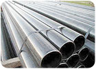
Steel casing ready to go. Photo courtesy of Burner Well Drilling Inc.
Casing Requirements
The diameter of the upper pump housing casing must provide sufficient clearance between the column pipe and casing to permit installation of a sounding tube or air line to measure depth to water. Extra clearance should be allowed for free operation of shaft-driven pumps and the electric cable for submersible pumps. No well is exactly straight and operation will be unsatisfactory if there is misalignment. Additionally, consideration should be given to the possibility of corrosion product buildup, which may lock the bowl to the casing. Consequently, pump-housing casing should have a minimum diameter at least 2 inches greater than the nominal diameter of the most efficient pump required for the desired yield.While it is true that increasing well screen diameter does not have much effect on production, there are strong reasons for specifying identical casing and screen diameters, with the exceptions of telescoped screen installations and under-reamed gravel envelope well design. Equal internal diameters facilitate well development and redevelopment processes. The possibility of damage due to dropping a pump or tools is minimized. Maintaining identical diameters prevents the possibility of excessive head loss through a restricted tube. Finally, it must be remembered that wells smaller than 6 inches in diameter are practically impossible to repair, and larger diameters facilitate later deepening, if required.
In wells deeper than 1,200 feet, a reduction of 4 inches in screen diameter can be practical. This generally is limited to high-capacity wells where the screen diameter is a minimum of 12 inches. The savings in screen and borehole costs may offset other considerations. This reduction normally begins at the bottom of the pump housing case.
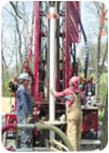
The wall thickness of a well casing is a critical factor to consider. Photo courtesy of Frontz Drilling Inc.
Wall Thickness
A more difficult dimensional selection of well casing is wall thickness. As mentioned earlier, certain stresses, such as the external hydrostatic force (drawdown), can be calculated, but others cannot. Fortunately, many years field experience under varied conditions provides useful information and guidance.The tensile (ultimate) strength of a metal is defined as the load in the direction of pulling it apart that is required to break it. Compression or crushing strength is the load in the opposite direction (pushing it together) required to deform it. This value is equivalent to the yield strength.
Steel strengths vary according to chemistry and manufacturing techniques. Pipe tensile and compression strengths are directly related to the tensile and yield strengths of the parent material, as well as its dimensions. Generally, wall thickness is the critical factor to consider.
The resistance of steel tubes to collapse under hydrostatic or similar squeezing forces is determined by outside diameter, wall thickness and ellipticity (out of roundness). In addition to these dimensional parameters, collapsing strength is influenced by some of the physical qualities of the material. Casing continuously deforms with increasing pressure until the critical pressure is reached. The casing is considered to be collapsed once deformation continues without additional pressure.
The dimensional parameters (wall thickness and ellipticity) are more closely related to collapsing strength than the physical parameter (yield strength). Use of higher strength steels does produce improvement in collapsing strength, but is more significant with respect to compression and tensile strength.
The collapsing strength of steel is proportional to the cube of its wall thickness. Therefore, a small increase in thickness provides a substantial increase in collapsing strength. Conversely, a small decrease in thickness results in a substantial decrease in collapsing strength. Also of importance to strength is pipe roundness.
Used or damaged pipe should never be installed in a water well. It should be kept in mind that unless there is a subsidence problem, most structural failures in wells occur due to collapsing forces.
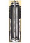
Conductor casing. Photo courtesy of Roscoe Moss Co.
Corrosion Resistance
As a component of well design, the effects of corrosion under the anticipated operating conditions should be examined. Metallic corrosion is a complex subject, but some generalizations are made here which may be helpful. First, well casings and screens are subject to different types and degrees of attack according to their location in the well. Because many ground waters are saturated with calcium carbonate, the screen section will tend to encrust rather than corrode, which promotes longevity but frequently requires periodic removal of buildups to restore production. In most wells, the greatest corrosion attack occurs in and just above the “splash zone” between the static water level and pumping level. The casing is exposed to a humid atmosphere or an alternate wetting and drying condition, which accelerates attack on steel. The pump column is similarly affected.With respect to well waters themselves, it generally is accepted that the presence of bicarbonate retards corrosion, sulfate and nitrate are neutral, and chloride accelerates corrosion. Concentrations of carbon dioxide of more than 50 milligrams per liter usually are corrosive. Water containing hydrogen sulphide should be checked for the presence of sulphate-reducing bacteria, which are highly detrimental to well screens. Acidic water may be severely corrosive, but the corrosion usually is uniform, rather than pitting. Consequently, well life may be greater than normally expected.
It is unfortunate that no one has developed a method of determining the life of material given the constituents of the water. Again, the best guide is experience. Throughout the United States, and in most regions of the world, there are ample well histories giving clear directions. There is no condition, when potable waters are produced, where adequate well life cannot be obtained through the use of proper well design and material selection.
Required well life depends upon a host of economic considerations. In most areas of the United States and elsewhere where waters generally are alkaline, 40-year life is not uncommon. Generally, 30-year life is a reasonable expectation.
With respect to steel casing, greater than average corrosion occurs in the most humid or alternating wet and dry zone. This is a form of atmospheric condition, and the use of heavier wall materials extends life considerably. Doubling wall thickness should extend life four or more times. Increasing wall thickness, however, has not proven to be much help with severely corrosive waters.
The addition of copper to steel so that its content reaches a minimum of 0.20 percent increases its atmospheric corrosion resistance by approximately two times. Specification of this quality material is shown as an alternative in all standard ASTM specifications for structural grade steels. Copper-bearing steel has been used as casing material in the southwestern United States for more than 90 years. Culvert steel also is copper bearing.
High-tensile, low-alloy steels have been in general use for many years. They are about 40 percent stronger than regular carbon steel. Atmos-pheric corrosion resistance of these materials in the corrosion-resistant grades is four to six times that of carbon steel, and two to three times that of copper-bearing steel. There also is some evidence to support the view that they offer greater longevity in the fully submerged area. However, where conditions are severely corrosive and carbon steels do not endure for at least 10 years, neither copper-bearing steels nor high-tensile, low-alloy steels should be used.
One of the advantages of most high-tensile, low-alloy steels is that their high strength is achieved through the use of alloying elements rather than additional carbon and manganese. If high-strength line pipe is considered for use, the following evaluation should be made: divide the manganese percentage by six, and then add it to the carbon percentage. If the sum exceeds 0.50 percent, problems may be encountered in field welding.
Regrettably, there is a substantial difference in cost as well as durability between high-tensile, low-alloy steels and the next most corrosion-resistant category - stainless alloys. Type 304 stainless steel (18% chromium, 8% nickel) has been found to offer complete protection in any potable water environment. This steel also is immune to acids used to remove encrustations. While frequently used in water wells, type 304 stainless probably represents overdesign and unnecessary extra cost, as grades containing lower percentages of expensive chromium and nickel do just as well in similar environments.
For saltwater wells (chloride concentrations greater than 500 mg/liter), the conventional selection is type 316 stainless steel. In most cases, type 304 is adequate, but has a tendency to pit.
Under conditions where selection of stainless steel in indicated, non-ferrous materials may be considered, particularly in shallow, smaller-diameter wells. Careful consideration should be made, however, of mechanical and other limitations of these materials.
Conventional pipeline coatings are not suitable for water well casings or screens. An exception, galvanizing, continues to protect a bare spot or “holiday.” Under acidic conditions, however, galvanizing does not offer sufficient additional well life to justify its cost.
Cathodic protection of water wells has been field-tested, but has not proven practical. The systems are expensive and require maintenance. More importantly, it is not feasible to protect the interior of any pipe structure by cathodic protection. Cathodic protection may be considered, however, for saltwater production wells.
Conductor Casing
Many wells require, for construction and occasionally protective reasons, the installation of a surface or conductor casing. Such casings range from 20 feet to 50 feet in length, although more may be required to reach an impervious stratum. Usually, surface casings for gravel envelope wells are 6 inches to 12 inches larger in diameter than the upper casing, and approximately 4 inches larger for non-gravel envelope wells. Wall thicknesses range from 0.1875 inch to 0.3750 inch, depending upon depth and diameter. The annular space between the casings may be grouted, as well as the annular space between the conductor casing and its borehole.Surface casing prevents the direct infiltration of polluted surface waters between the casing and borehole, and stabilizes the upper formations, which usually are unconsolidated, during drilling, completion and use.
ND
Report Abusive Comment