A wide range of directional drilling units exists in the marketplace. The smallest drilling rigs typically are used for the installation of telecommunication residential service cables. Larger rigs are capable of installing pipelines up to 48 inches. Installation range is determined by many parameters, including rig size, soil conditions and product diameter. Installations exceeding 6,000 feet have been completed successfully.
Getting Started
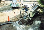
The drill rig is off-loaded and positioned over the bore centerline a sufficient distance behind the entry point to allow for the carriage height and entry angle, such that the drill bit will enter the ground at the correct location and angle. Depending on the rig size and entry angle, this distance may be 3 feet to 20 feet behind the entry point. The entry angle usually is between eight degrees and 16 degrees, although entry angles of up to 20 degrees have been used on some large diameter projects. A small pit usually is excavated over the entry point, using a backhoe or shovel. If the entry point is within a paved area, the pavement must be removed using a jackhammer or concrete saw, depending on the owner/engineer's requirements. Machines often are staked down, using the powered rotating augers located on either side of the spindle at the front. Care must be exercised to avoid contact with underground utilities during stake-down, and to ensure sufficient reaction can be developed for thrust and pullback.
While the equipment is being set up, the entry and exit areas should be delineated using traffic cones and construction tape or flagging. The work areas should be laid out in accordance with the specifications and traffic control plans. Fencing should be installed to restrict access and ensure public and worker safety. If the equipment cannot fit into the allowable entry area, the owner/engineer should be contacted to resolve the problem. Likewise, the exit area must accommodate the product reel and trailer, or the pipe laid out for welding and fusing. If the specified exit area is insufficient, the contractor should notify the owner/engineer to resolve the problem. Thorough planning and a pre-bid or pre-construction walkover site inspection should avoid potential conflicts such as insufficient work areas.
Equipment and Materials
A list of equipment and materials necessary for the job should be prepared in advance. Before equipment is dispatched to the job site, it should be serviced, inspected for damage and repaired as necessary. This includes bits, reamers, swivels, hoses gauges, etc. Drill pipe should be inspected for damage to the pipe and threads and replaced as necessary. The electrical strike-sensing systems should be checked to ensure it is in good working condition. Anchoring requirements should be determined. Appropriate types and quantities of drilling fluid additives should be on hand, including any special additives or components for dealing with excessive water hardness, high or low pH, or brackish conditions. Simple test should be conducted to ensure the water supply is suitable. Where possible, procure a secured area near the job site for staging all equipment and materials. Ensure that everything needed is on hand before beginning the bore. As it is unloaded on-site, the equipment and materials should be checked off against the checklist prepared for the job.
Pilot Bore and Tracking
Prior to drilling, the drilling fluids should be mixed and sufficient quantities should be available to complete the pilot bore, pre-reaming and reaming passes. The actual quantity of drilling fluids that must be pumped to remove cuttings and maintain a stable open bore usually will exceed the bore volume - sometimes by substantial amounts, depending on ground conditions and other factors.When the drill rig is properly set up and anchored and drilling fluids mixed, the pilot bore can be initiated. To make entry of the drill string easier, a small entry pit usually is excavated. The pit facilitates entry of the bit at the proper angle and helps contain drilling fluids. The pilot bore should begin with the slanted head at 6 o'clock to facilitate entry without deflection upward or to one side. It may be necessary at times to position a backhoe bucket on top of the drill head as it enters the ground to facilitate proper entry.
The pilot bore is drilled along the planned alignment from entry to exit. The planned path should have the fewest bends possible. This prolongs drill string life and minimizes pullback problems. The ideal bore begins with a straight, tangent section inclined at the angle of entry to the ground surface. The straight tangent section is needed to gain sufficient depth to provide steering reaction and depth of cover. The drill head then is steered in an upward sweeping curve transitioning into a horizontal segment before turning another upward sweeping curve, and continuing to the exit point along a straight tangent segment inclined at the angle of exit (5-10 degrees) with the ground surface. Another pit usually is excavated at the exit point to facilitate containment of drilling fluids and any of the pipe or cable during pullback operations.
The type of drill bit used will vary depending on ground conditions and contractor preferences. The method of steering also may vary, depending on whether the ground is relatively soft soils or rock.
The drill head is tracked by monitoring an electromagnetic signal transmitter mounted in the drill head to the receiver at the surface. Alternatively, it may be tracked with a wireline or wireless non-walkover system. The drill locator determines drill head location and calculated depth, drill head inclination (or tool face angle) and orientation of the slanted face. The drill locator provides the tracking information to the driller or provides instructions to the drill rig operator for steering.
Whether a walkover or non-walkover system is used, the objective is to calculate the actual location of the drill head as the bore progresses. Appropriate steering inputs can then be made to keep the bore along the designed drill path. Steering corrections should begin promptly when deflections are detected or changes in the bore path's direction are needed. The corrections should be gradual and remain within the allowable bend radius. To avoid over-steering and undulations in the bore path, steering corrections should end just before the correction is completed.
Sometimes it is necessary to pull the drill head one or more drill pipe lengths to increase steering response and achieve desired corrections. The drill head also may be retracted when circulation is lost to try to re-establish circulation.
During the pilot bore, the surface should be closely monitored for inadvertent drilling fluid returns. Any fluids should be cleaned up promptly. Drilling practices may require modification to reduce the risk of continued returns.
At the completion of the pilot bore, the drill bit and transmitter or steering tool usually are removed in preparation for reaming. Any excess fluids or cuttings around the exit should be cleaned up to enhance safety and avoid runoff to storm drains or streets.
Reaming/Hole Enlargement
If the pilot bore is to be enlarged, a reamer hole opener is attached to the drill pipe, and the drill pipe is pressurized to ensure the jets are open. The reamer then is rotated and pulled (or pushed in some cases) back through the pilot bore to enlarge the bore in one or more reaming passes. The number of reaming passes depends on the diameter of the product compared to the diameter of the pilot bore, ground conditions and driller preferences. The number of reaming passes commonly varies from zero to three; however, more passes may be necessary. For example, if durable product is being pulled, reaming may be unnecessary; if 48-inch-diameter pipe is being pulled, several reaming passes may be required.
In loose or soft soils, the number of required reaming passes typically will be less than if hard soils or rock are encountered. This primarily is due to torque limitations, cleaning plant capacity and pump capacity. Reaming may be accomplished by pulling or pushing the reaming tool through the hole. The final bore diameter must be larger than the product diameter to reduce frictional pullback loads and to facilitate flow of the drilling fluids around the product. As a rule of thumb, the final bore diameter should be the lesser of the product diameter plus 12 inches or 1.5 times the diameter of the product. For small-diameter products (8” or less), the reamer should provide a minimum 2-inch annular space, i.e., the reamed diameter should be 4 inches larger that the product diameter. However, different contractors will have their own preferences, based on their experiences under various conditions.

Layout, Fabrication and Testing
The product is prepared for installation while the bore is being reamed. The specific steps involved will depend on project requirements, intended function of the product and product material. Generally accepted procedures include:
- Notify engineer of plan and schedule for layout, fabrication and testing.
- Ensure that the layout area is relatively clean, flat and free of debris, sharp rocks or other objects that could damage the product.
- Ensure that the correct product (material, diameter, thickness and length) is on-site, meets or exceeds specified requirements and is free of debris and material defects. If not, replace any incorrect or defective materials.
- Ensure that proper fabrication and handling equipment is on-site for fusing or welding sections of the product, and that trained, experienced personnel are available for this task. Follow the manufacturer's recommendations during welding or fusing operations, including temperature control for cold-weather butt-fusing operations.
- Inspect fabricated product for defects in workmanship and repair/replace any defects.
- Ensure that the proper testing apparatus is on-site and that field personnel understand the test procedure, timing and sequence of testing, and minimum performance requirements as stated in contract documents.
- Perform quality control tests and carefully document results, as required by the contract documents, prior to installation.
- Record any failures, and repair and retest until fabricated product passes all applicable tests.
For specific fabrication and testing guidance, manufacturer's recommendations and the contract documents should be consulted.
Pullback
After fabrication and pre-installation testing have been completed, the product is prepared for pullback. A pulling head is attached to the product. A swivel is installed between the reamer and the pulling head to prevent rotation of the product. The product must be properly positioned and supported to enter the bore. It may be necessary to support the product on rollers or with a crane to prevent damage to the product during pullback. Breakaway swivels also may be installed between the product and swivel to prevent overstressing of the product as it is installed. Breakaway swivels are designed to fail before the pullback load exceeds the safe capacity of the product. Pullback should be completed without interruption, to reduce risk of becoming stuck in the bore.Connections
The general contractor, owner or a party other than the directional drilling contractor typically constructs connections of the new product to existing cables or pipes. The connections may vary from cable splices in a vault to pipe couplings, elbows or tees. The primary responsibility of the directional drilling contractor is to begin and terminate the HDD installations at the locations shown on the plans, and to cap the product as required in the specifications. If the exit differs from that called for on the plans, the directional drilling contractor is responsible for ensuring that the connection can be made. This may require a short section to be re-drilled prior to installation, or a short open-cut section if done after installation.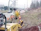
As-builts/Operator Logs
The as-built drawings typically are produced by the construction management firm or owner, using the design drawings. The directional drilling contractor will mark the plans to indicate any and all vertical and horizontal deviations between the design and the actual bore. The owner may require submission of complete as-built plans and the operator logs prior to final payment. It is good practice to update the as-built drawings on a daily basis - to exercise quality control and to check the as-built revisions prior to submittal. As the underground environment becomes increasingly crowded, accurate as-built drawings become invaluable for future maintenance and new construction. Maps or as-builts created by remote mapping systems also are very helpful.
The operator logbook should be maintained and updated daily by the drill rig operator or superintendent. The logbook should include the drill locator's notes and records for bores using steering and tracking systems. An operator logbook should include pipe number, depth, pitch, steering commands and notes. For larger-diameter or high-risk bores, the log also may include rig performance parameters such as thrust, pullback, torque, drilling fluid circulation, drilling fluid composition, ground conditions, potential obstructions or objects encountered, time the shift started and ended, footage during the shift and other parameters. The logs should be legible, accurate and should be submitted to the inspector, owner or construction manager, as required by the contract documents.
Site Restoration
After the product is installed, the entry and exit pits are cleaned of drilling fluids and cuttings and backfilled with native soil or select backfill that is placed and compacted in accordance with contract documents. Surface debris, trash, worn out or broken tools and equipment must be removed. Surface grading, seeding and re-vegetation may be required for undeveloped areas. For developed areas, surface restoration may include replacement and compaction of pavement sub-base and base materials and the paving course. Reconstruction of sidewalks, curbs and gutters that have been damaged by the contractor's operations will be required. The objective is to leave the area in pre-existing or better conditions. Often, payment of final closeout invoices and retained amounts is contingent on proper site restoration and clean up. NDThe HDD Consortium
Members of the horizontal directional drilling industry have long recognized the importance of having knowledgeable and competent project personnel. Four years ago, six leading organizations joined forces to address the need for a consensus, industry-led education and training program for users of HDD technologies. The six organizations:
- Directional Crossing Contractors Association
- Distribution Contractors Association
- Equipment Manufacturers Institute
- National Utility Contractors Association
- North American Society for Trenchless Technology
- Power & Communication Contractors Association
The HDD Consortium developed “HDD Good Installation Practices Guidelines,” from which this article is excerpted. The guidelines were prepared under the leadership of principal authors Sam Ariaratnam, David Bennett and Casey Como.
Report Abusive Comment