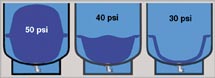
Figure 1. Captive-air tank water chamber during the drawdown cycle. (Click on the image for a larger version.)
The primary function of the pressure tank in a pumped water system is to protect the pump motor. This is accomplished by storing water under pressure so the pump does not have to come on every time there is a small, intermittent demand for water. The amount of usable water stored in a pressure tank is called the drawdown, and it is the amount of water that can be drawn from the tank between the time the pressure switch cuts out, turning off the pump, and it cuts back in, turning on the pump. We showed how to calculate drawdown in the February 2006 issue of this publication. Figure 1 depicts what goes on inside a captive-air pressure tank as the water is drawn out and the pressure drops.
Pressure tanks are sized according to the flow capacity of the pump, with enough drawdown to allow the pump to be off for a minimum of 1 minute between run cycles, to let the motor cool, as recommended by the motor manufacturers. A 10-gpm pump would require a pressure tank with 10 gallons of drawdown, and so on.
There are two types of pressure tanks, captive-air tanks (also called pre-charged, diaphragm or bladder tanks), and conventional tanks (also known as hydro-pneumatic, galvanized, ASME and epoxy-lined tanks). Using the term “hydro-pneumatic” to describe a conventional tank is a bit of a misnomer. All pressure tanks used in the ground water industry are hydro-pneumatic, meaning they contain water (hydro) and air (pneumatic). In this article, we will use the terms “captive air” and “conventional” to differentiate the two types of tanks.
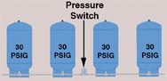
Figure 2. A basic rule to follow is to make sure the pressure switch sees the same pressure as the tanks. Proper pressure switch placement. (Click on the image for a larger version)
The largest commonly available captive-air tank has a total capacity of 119 gallons. The size of a pre-charged captive-air tank is limited by federal highway regulations, which require special permits to transport pressurized tanks having a capacity 120 gallons or more. The drawdown or usable water available from a 119-gallon tank operating in conjunction with a 30/50 pressure switch is 36.8 gallons according to Boyle's Law. Following the “1-minute run-time between cycles” rule mentioned above, a 36-gpm pump would be the largest pump you could use with such a tank. What do you do then if you have a larger pump? There are several options.
Conventional tanks are available in virtually any size and are a viable option. They are, however, expensive and require the use of an air-charging system to replace the air that is absorbed into the water. For this reason, the use of multiple captive-air tanks is gaining in popularity. It is not uncommon to see six or eight captive-air tanks lined up in row to provide the necessary drawdown for a large pump. For instance, six 119-gallon tanks would provide enough drawdown for a 200-gpm pump (6 X 36.8 = 220.8 gallons). The size and number of tanks you end up with will depend on economics and available real estate for you tanks. It might turn out that eight of the more common - and less expensive - 85-gallon tanks with a drawdown of 26.4 gallons would be cheaper than six 119-gallon tanks, but be sure to figure in the cost of the manifold system in your total.

Figure 3. Place the pressure switch as close as possible to the center of the tanks; proper pressure switch placement. (Click on the image for a larger version)
Plumbing a Multi-tank System
It is very important that a multi-tank system be plumbed properly for it to work properly. There are two common mistakes made on these systems - locating the pressure switch in the wrong place and the under-sizing of the interconnecting piping. The two basic rules to follow are 1) make sure all the tanks see the same pressure while the pump is running, and 2) make sure the pressure switch sees the same pressure as the tanks. To comply with rule 1, use a large enough manifold pipe to assure the flow velocity does not exceed 6 feet per second. This will keep the pressure drop to a minimum from one end to the other and help assure uniform pressure is the entire tank system.To comply with rule 2, place the pressure switch as close as possible to the center of the tanks. Figures 2 and 3 illustrate proper pressure switch placement.
When properly designed and installed, the use of multiple residential-type pressure tanks in a larger high-capacity system offers a viable alternative to a single large conventional pressure tank. Next time you need more tank capacity, give this alternative some consideration.


Report Abusive Comment