Complex investigations are made only after a thorough analysis has been made of existing or easily acquired data. Results from ground water and foundation seepage studies provide data needed to design dewatering and seepage control systems at construction projects, indicate the potential for pollution and contamination of existing ground water resources due to project operation, show potential for interference to aquifers by the construction of a project, and determine the chemical and biological quality of ground water and that relationship to project requirements. Investigation and continued monitoring of ground water fluctuations are key dam safety issues.
Wells - Existing wells located during field geologic reconnaissance should be sounded or water levels obtained from the well owners. Pumping quantities, seasonal variations in ground water and pumping levels, depths of wells and screen elevations, corrosion problems and any other relevant information should be acquired wherever available. Any settlement records attributable to ground water lowering from pumping should be obtained. This information should be compared with water well records obtained during preliminary studies to develop a complete hydrologic picture for the project area.
Borings - Water levels recorded on drilling logs are another source of information. However, they may not reflect true water levels, depending on soil types and time of reading after initial drilling. The influence of drilling fluids on water level readings should be kept in mind when evaluating boring data. Loss of drilling fluids can indicate zones of high permeability. Where ground water level information is needed, installation of piezometers or observation wells in borings should be considered.
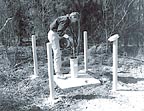
Piezometers and observation wells - The most reliable means for determining ground water levels is to install piezometers or observation wells. Piezometers measure excess hydrostatic pressures beneath dams and embankments. All information developed during preliminary studies on the regional ground water regime should be considered in selecting locations for piezometers and observation wells. All piezometer borings should be logged carefully and "as built" sketches prepared that show all construction and backfill details.
The selection of the screened interval is critical to the information produced, since the waterlevel recorded will be the highest of all intervals within the screen/filter length. Careful evaluation of the conditions encountered in the hole with regard to perched or confined aquifers is essential to a sensible selection of the screened interval and interpretation of the data. One of the greatest benefits of a piezometer or observation well is that it allows for measurement of fluctuations in piezometric levels over time. To take advantage of this benefit, it is necessary to provide for periodic readings. This can be accomplished through manual reading by an automated system, depending on the location and critical importance of the area being monitored.
Other information that can be derived from observation wells and piezometers are temperature and water quality data. Tracer tests can sometimes be conducted to determine the direction and rate of ground water flow.
Springs and surface water - The water elevation, flow rate, and temperature of all springs located within the project area should be measured. Water should be sampled for chemical analysis to establish a baseline level. Soil or rock strata at the spring should be evaluated to locate permeable horizons. Flow rates at springs should be measured during dry and wet seasons to determine the influence of rainfall on seepage conditions. The elevation of water levels in lakes and ponds should be measured during the wet and dry seasons to evaluate the extent of surface water fluctuations.
Geophysical methods -Geophysical methods, such as seismic refraction, can be used to determine the depth to saturated material. Depending on the accuracy required and the accuracy of the method, a minimal number of piezometers should be installed to verify the geophysical data. Surface resistivity surveys can indicate the presence of and depth to water. Ground penetrating radar can also be used to detect the presence and location of ground water.
Tracer testing - In some areas, especially karst terrains, it is of particular interest to determine flow paths in the ground water system. Although complex, flow paths in karst, where seepage velocities are high, can be evaluated by conducting tracer tests using either environmentally benign dyes or biological tracers such as pollen. The tracer element is introduced into a boring or other access points and monitored at an exit point such as a spring. The travel time from the introduction to detection is recorded. Numerous tests at different locations can be run and a picture of the ground water flow regime developed.

Permeability Testing
Permeabilities of foundation materials can be determined from slug and pumping tests in piezometers and wells, laboratory tests of undisturbed samples and pressure tests in rock foundations. Fracture and joint analysis is important in evaluating permeability of rock foundations.Tests in piezometers or wells - Permeability tests can easily be made in piezometers or wells. They should be performed as part of piezometer installation procedures, both to obtain permeability information and to assure that the piezometer is working satisfactorily. Appropriate piezometer permeability tests are constant head, falling or rising head, and slug. The information obtained is representative of a smaller volume of material than that tested in pumping tests. However, procedures are simple, costs are low, and results may be useful if interpreted with discretion.
Pumping tests - Pumping tests are the traditional method for determining permeability of sand, gravels or rock aquifers. Observation wells should be installed to measure the initial and lowered ground water levels at various distances from the pumped well. At known or suspected hazardous, toxic and radiological waste sites, disposal of pumped water is a major consideration.
Pumping tests usually are desirable for the following:
- large or complex projects requiring dewatering
- design of underseepage systems for dams or levees
- special aquifer studies
- projects where water supply will be obtained from wells
- projects immediately downstream from existing embankments
Permeability of rock - Most rock masses contain, in addition to intergranular pore spaces, complex interconnecting systems of joints, fractures, bedding planes and fault zones that, collectively, are capable of transmitting ground water. Fracture or joint permeability normally is several magnitudes higher than the matrix permeability of the discrete blocks or masses of rock contained between the joints. The permeability of some rock masses, such as sandstones and conglomerates, is governed by interstitial voids similar to that of soils. Secondary weathering and solutioning of limestones and dolostones may produce large void spaces and exceptionally high permeabilities. Although the permeability of rock results from interconnecting systems of joints, fractures and formational voids, the equivalent rock mass permeability can frequently be modeled as a uniform porous system.
Although it is necessary to keep the hydrologic model manageable, the shortcoming of this approach is that most rock masses are anisotropic with regard to permeability. The influence of this on a practical level is that it is easy to over- or underestimate the ground water effects in rock. As an example, if a pumping test is conducted with monitoring wells oriented along a line perpendicular to the predominant water-bearing joint set, the results will underestimate the radius of influence along the joint set. Therefore, the layout of pumping tests must be well thought out beforehand. At least a preliminary fracture and joint analysis should be conducted prior to laying out a pump test.
Fracture and joint analysis - Because joint or fracture permeability frequently accounts for most of the flow of water through rocks, an accurate description of in-situ fracture conditions of a rock mass is critical to predicting performance of drains, wells and piezometer responses. Joints typically occur in sets which have similar orientations. There may be three or more sets of joints in a rock mass. Joint sets that occur in the rock mass at the site should be identified and the preferred orientation and range in orientation of each joint set recorded. Features such as joint orientation, spacing, joint width and the degree and type of secondary mineral filling should be carefully noted for each joint set. Once all joint sets of a site have been identified and evaluated, their relative importance to ground water flow should be assessed. Joints and fractures can be evaluated by developing the structure and stratigraphy of the site from accessible outcrops and from borehole logs.

Pressure Tests
Pressure tests are performed to measure the permeability of zones within rock masses. The test results are used in assessing leakage in the foundation and as a guide in estimating grouting requirements. Pressure tests are typically conducted during exploratory core drilling and are a relatively inexpensive method of obtaining important hydrogeologic information about a rock mass. Hydraulic pressure testing should be considered an integral part of the exploratory core drilling process in all cases where rock seepage characteristics could affect project safety, feasibility or economy. The testing interval is typically 5 feet to 10 feet, but may be varied to fit specific geological conditions observed during the core drilling operations. Zones to be tested should be determined by:
- examining freshly extracted cores
- noting depths where drilling water was lost or gained
- noting drill rod drop
- performing borehole or TV camera surveys
- conducting downhole geophysical surveys.
In rock with vertical or high angle joints, inclined borings are necessary to obtain meaningful results.
Pressures applied to the test section during tests should normally be limited to 1 psi per foot of depth above and 0.57 psi/foot of depth below the piezometric surface. The limit was established to avoid jacking and damage to rock formations. The limit is conservative for massive igneous and metamorphic rocks. However, it should be closely adhered to for tests in horizontally bedded sedimentary and other similar types of formations. Naturally occurring excess water pressures (artesian) should be taken into account in computations for limiting test pressures. Where the test intervals are large, a reduction in total pressure may be necessary to prevent jacking of the formation within the upper portion of the test section.
An important, but often unrecognized, phenomenon in pressure testing is joint dilation and contraction as pressure is applied and released. In the case of a dam project, it is desirable to use pressures that will correspond to future reservoir conditions. Joint dilation can frequently be observed by conducting a "holding" test. The fall in pressure is observed and a plot of pressure versus time is made. The pressure should quickly drop to near the surrounding piezometric level if the joint openings remain the same width. The common observation of a slow pressure decay in pressure holding tests indicates joint closure with reduction in pressure.
Qualitative evaluations of leakage and grout requirements can be made from raw pressure test data. Most analyses of this type assume laminar flow rather than turbulent flow. This assumption can be verified by conducting pressure tests on the same interval at several different pressures. If the water take is directly proportional to the total applied pressure, laminar flow can be assumed. If pressure test data are converted into values of equivalent permeability or transmissivity, calculations can be performed to estimate seepage quantities. Wherever possible, such results should be compared with data from completed projects where similar geologic conditions exist.
Report Abusive Comment