
Direct-push technology (DPT) ground water sampling equipment generally falls into one of two broad categories:
- Point-in-time ground water samplers: These tools or devices, also referred to as “temporary samplers” or “grab samplers,” are used to rapidly collect samples to define ground water conditions during one sampling event. They usually are less than 2 inches (O.D.), and generally are constructed of steel or stainless steel. Direct-push methods (percussion or static weight) are used to advance point-in-time samplers below the static water level in unconsolidated formations. Generally, ground water flows into the sampler from an exposed screen under ambient hydrostatic pressure. Ground water may be collected from the sampler using bailers or pumps, or the sampler may be retracted to the surface to obtain the water sample. Once sampling is completed, these devices are removed, and the boring should be abandoned in accordance with local regulations.
- DPT-installed ground water monitoring wells: These monitoring wells are installed by direct-push methods to permit short-term or long-term monitoring of ground water. They usually are 2 inches in diameter or less, and constructed of PVC and/or stainless steel. Since monitoring wells are installed for periods of several months to several years, the annulus of the boring around the well casing usually is sealed to prevent migration of contaminants into the aquifer. Surface protection is required to prevent tampering with the well. A slotted or screened section permits ground water to flow into the well under ambient hydrostatic pressure. Ground water may be collected from monitoring wells using bailers, various pumps or passive sampling devices.
Point-in-time sampling tools typically are used during site characterization to identify plume boundaries or hot spots. They cannot be used for long-term monitoring or trend analysis since the boreholes need to be decommissioned upon completion of sampling. In contrast, temporary and permanent monitoring wells typically are used to provide trend analysis of contaminant ground water concentrations over an extended period of time. DPT can be used to install small-diameter (e.g., up to 2 inches O.D.) monitoring wells.
Ideally, both DPT point-in-time and monitoring well ground water sampling equipment should be used together to maximize their effectiveness. Point-in-time sampling techniques generally are better for identifying plume boundaries, hot spots, preferred pathways or other monitoring points of interest. Once this information is collected, DPT monitoring wells, as well as conventional monitoring wells, can be optimally placed to provide project teams with the most useful monitoring data.
Point-in-time Sampling
A variety of point-in-time ground water sampling tools are available for site characterization, including:- sealed-screen sampling;
- multi-level sampling (or vertical profiling); and
- open-hole sampling.
With these techniques, the time needed to retrieve the sample will vary according to the hydraulic conductivity of the sampling zone. In general, sampling within coarse-grained sediments takes minutes, while fine-grained sediments can take several hours or more. In situations where slow recharge inhibits the timely collection of ground water samples, the sampler may be left in place to recharge while the DPT rig is moved to a new sampling location.
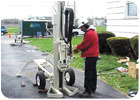
Sample collection in a residential neighborhood.
Sealed-screen Samplers
Sealed-screen samplers typically consist of a short (e.g., 6-inch to 3-foot) screen nested within a sealed, watertight tool body. Because the screen is not exposed to the formation as the sampler is advanced into the subsurface, the screen does not become plugged or damaged. In addition, the potential for cross-contamination is greatly reduced and a true depth-discrete sample that is representative of the target sampling zone can be collected. The sample volume collected with some sealed-screen samplers is limited by the volume of the sample chamber.To collect the sample, the sealed-screen sampler is advanced to the target sampling depth and the protective outer rod is retracted, exposing the screen to ground water. Ground water flows through the screen under the hydraulic head conditions that exist at the depth and into the drive rods or sample chamber. O-ring seals placed between the drive tip and the tool body help ensure that the sampler is watertight as it is driven to the target sampling interval. The integrity of the seal often can be checked by lowering an electronic water-level indicator into the sampler prior to retracting the protective outer rod.
Sampling fine-grained formations may be difficult because of the long time it takes to fill the sampler with ground water. Sample collection times in formations with low hydraulic conductivity may exceed several hours for some tools, compared to several minutes or tens of minutes in formations of high-to-moderate hydraulic conductivity. However, to avoid downtime, the samplers can be left in the borehole to recharge while the installing rig moves off the hole to another location to sample. To decrease sample collection time, samples can be collected from samplers with longer, 30- to 42-inch screens while the tool is downhole. A bailer or pump is needed to collect the sample from the target zone.
Sealed-screen samplers generally are limited to collecting one sample per advance of the sampler. However, depending upon the system used, multi-level sampling in a single borehole can be accomplished with sealed-screen samplers by retrieving the sampler and decontaminating it or replacing it with a clean sampler before reentering the hole to collect another sample.

Interest in understanding how DPT ground water collection methods compare with traditional monitoring well sampling methods has steadily increased since the mid-1980s, when DPT first started being used for this purpose. Photo courtesy of Central Associated Engineers Inc.
Multi-level Samplers
Multi-level samplers, most of which are exposed-screen samplers, are DPT equipment capable of collecting ground water samples at multiple intervals as the sampling tool is advanced, without having to withdraw the tool for sample collection or decontamination. The terminal end of a typical multi-level sampling tool has a 6-inch- to 3-foot-long screen made up of fine-mesh, narrow slots or small holes. The screen remains open to formation materials and water while the tool is advanced. This allows samples to be collected either continuously or periodically as the tool is advanced to vertically profile ground water chemistry and aqueous-phase contaminant distribution.Multi-level samplers can be used to measure water levels at discrete intervals within moderate- to high-yield formations to assist in defining vertical head distribution and gradient. Additionally, some of these tools can be used to conduct hydraulic tests at specific intervals to characterize the hydraulic conductivity in formation materials to identify possible preferential flow pathways and barriers to flow.
A drawback to multi-level sampling is the possible drag-down by the screen of contamination from zones above the desired sampling interval. The Waterloo Profiler minimizes the potential for cross-contamination. It uses a 6-inch long, uniform diameter, stainless steel sampling tool into which several inlets or sampling ports have been drilled and covered with fine-mesh screen. As the tool is advanced, distilled or deionized organic-free water is slowly pumped down tubing that runs inside the drive rod and leads to the sampling ports in the tool. The water keeps ground water from entering the tool while it is advanced. A peristaltic pump typically is used for depths less than 25 feet; a double-valve pump can be used for sampling at greater depths.
After the first target interval is reached, the flow of the pump is reversed and the sampling tube is purged so water representative of the aquifer is obtained. After the sample is collected, the pump is reversed, and distilled or deionized water is again pumped through the sampling ports. The tool then is advanced to the next target interval where the process is repeated.
Several field studies have demonstrated that the Waterloo Profiler is capable of providing a very detailed view of contaminant plumes - particularly in complex stratified geological materials - without the effects of drag-down and the cross contamination of samples. However, because a peristaltic pump typically is used to collect samples when the sampling depth is less than 25 feet below ground surface, there may be a negative bias in samples collected for analysis of VOCs or dissolved gases. To avoid this potential bias, VOC samples should be collected in-line, ahead of the pump, and a sufficient volume of water should be pumped through the system to account for the initial filling of the containers when a negative head space was present.
Another multi-level sampler, the VERTEK ConeSipper, attaches directly behind a standard cone penetrometer to collect ground water as the cone penetrometer testing is advanced. An inert gas flows to the ConeSipper to control the rate of sample collection and to purge and decontaminate the device down hole. The ConeSipper is equipped with two filters, which help minimize turbidity in the samples.
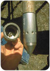
A Waterloo Profiler allows for the collection of multiple-depth discrete ground water samples. Photo courtesy of Precision Sampling Inc.
Open-hole Sampling Methods
Open-hole sampling is conducted by advancing drive rods with a drive point to the desired sampling depth. Upon reaching the sampling depth, the rods are withdrawn slightly, which separates them from the drive tip and allows water to enter the rods. The water can be sampled by lowering a bailer into the rods or by pumping. The open-hole method is only feasible within formations that are fairly cohesive, otherwise the formation may flow upwards into the rods when they are withdrawn, preventing samples from being collected.With single-rod systems, open-hole sampling can only be conducted at one depth within a borehole because the borehole cannot be flushed out between sampling intervals, and cross-contamination may occur. Dual-tube systems, on the other hand, can be used to conduct multi-level sampling.
Dual-tube samplers typically are advanced into the subsurface to collect continuous soil cores; however, ground water samples can be collected at the end of each core run. Dual-tube samplers have an outer casing that is driven to the target soil coring depth. The outer casing holds the hole open and seals off the surrounding formation as an inner rod (with a sample liner for soil sampling) is lowered into the outer casing and both are driven into the undisturbed formation below. Once the sole core is retrieved, ground water can be sampled by lowering a bailer or pump into the outer casing. The borehole can continue to be advanced so that multiple ground water samples can be retrieved from multiple depths in the same borehole. The water should be purged from the casing with subsequent advances of casing and inner rod so that ground water from overlaying intervals do not cross-contaminate the sample.
The amount of water that needs to be purged depends upon the type of sampling equipment that is used. For pumping systems, purging procedures similar to those designed for wells (low-flow purging) should be used. If bailers are used, then it is important that all the water contained in the outer casing be removed to ensure that the water the bailer is passing through comes from the interval of interest. The accepted procedure for traditionally completed wells when bailers are used is to remove at least three volumes of water and measure water quality indicators (e.g., pH, specific conductance) until they stabilize. The use of a bailer in this situation may preclude the collection of some parameters that may be sensitive to the iron in the outer casing.
A dual-tube profiling system has been developed so that a simple screen can be inserted through the cutting shoe of a dual-tube soil sampling. This system enables the operator to collect soil samples and then insert a screen at selected intervals, which they then can use for sampling or conducting slug tests to locate preferential migration pathways. This system also allows for bottom-up grouting to assure proper boring abandonment.
DPT Monitoring Well Installation
A variety of DPT methods are available for installing temporary or permanent monitoring wells. The two main installation methods used are exposed-screen and protected-screen wells. As with conventional well installations, hydraulic connections should not be created between otherwise isolated water-bearing strata. In addition, precautions should be taken to minimize turbidity during the installation of filter packs and the development and sampling of wells.
Pre-packed well screen being installed. Photo courtesy of Geoprobe Systems.
Exposed-screen Methods
With exposed-screen well installation methods, the well casing and screen are driven to the target depth using a single string of rods. Because the screen is exposed to formation materials while it is advanced, proper well development is important to remove soil from screen slots. This method is not recommended for installing well screens within or beneath contaminated zones because drag-down of contaminants with the screen may cross-contaminate sampling zones and make acquisition of samples representative of the target zone impossible. Exposed-screen well installation methods should only be used in upgradient areas that are known to be uncontaminated. Also, some states prohibit allowing the formation to collapse around a well screen in the construction of a monitoring well. Therefore, state regulations should be consulted before selecting exposed-screen techniques.In one type of exposed-screen installation, the PVC well screen and casing are assembled and placed around a shaft of a drive rod connected to a metal drive tip. The casing and screen, which rest on top of the drive tip, are advanced to the target depth by driving the rod to avoid placing pressure on the screen. The drive tip slightly enlarges the hole to reduce friction between the formation and the well screen and casing, and remains in the hole, plugging the bottom of the screen. The filter pack surrounding the well screen commonly is derived from formation materials that are allowed to collapse around the screen. Rigorous well development improves the hydraulic connection between the screen and the formation, and generally is necessary to remove formation fines and the effects of well installation, which may include borehole smearing or the compaction of formation materials. Due to the very small annulus (if any) that surrounds a well constructed using the exposed-screen method, it generally is not possible to introduce a filter pack or annular seal from the surface.
Exposed-screen methods also can be used to install well points - simple wells used for rapid collection of water level data, ground water samples and hydraulic test data in shallow unconfined aquifers. Well points generally are constructed of slotted steel pipe or continuous-wrap, wire-wound, steel screens with a tapered tip on the bottom. They can be driven into unconsolidated formations and used for either point-in-time sampling and decommissioned after the sample is collected, or left in place for the duration of the sampling program - possibly requiring the installation of a seal to prevent infiltration of water from the ground surface to the screened interval.
The optimum conditions for well point installations are shallow sandy materials. Predominantly fine-grained materials such as silt or clay can plug the screen slots as the well point is advanced. Because well points are driven directly into the ground with little or no annular space, the formation materials are allowed to collapse around the screen, and the well point needs to be developed to prepare it for sampling.
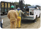
DPT can be used to meet a variety of data quality requirements for a wide range of site conditions. Photo courtesy of ESN North Atlantic.
Protected-screen Installations
When installing a protected-screen well, the well casing and screen are either advanced within or lowered into a protective outer drive rod that already has been driven to the target depth. Once the well casing and screen are in place, the drive rod is removed. Alternatively, the casing, screen and a retractable shield may be driven simultaneously to the target depth. Once in place, the screen is exposed and the entire unit remains in the ground. If there is sufficient clearance between the inside of the drive rod and the outside of the well casing and screen, a filter pack and annular seal may be installed by tremie from the surface as the drive casing is removed from the hole. Several filter packing and annular sealing approaches are available, depending on the equipment used for the installation. Regardless of the method of installation, the filter pack should be sized appropriately to retain most of the formation materials.The most common protected-screen method for installing DPT wells is to advance an outer drive casing equipped with an expendable drive tip to the target depth. The well casing and screen then are assembled, lowered inside the drive casing, and anchored to the drive tip. The drive casing seals off the formations through which it has been advanced, protecting the well casing and screen from clogging and from passing through potentially contaminated intervals. The position and length of the screen should be selected to match the thickness of the monitoring zone, which can be determined by using additional information, such as CPT logs or continuous soil boring logs.
When DPT wells are installed in non-cohesive, coarse-grained formations, the formation can be allowed to collapse around the screen (if this technique is not prohibited by state well installation regulations) after it is placed at the target depth since turbidity problems are unlikely. When turbidity is likely to pose a problem for ground water sample quality, a number of methods for installing filter packs are available. The filter pack can be poured or tremied into place as the drive casing is removed. Depending on the relative size of the drive casing and well, however, it may be difficult to introduce filter pack or annular seal materials downhole unless the hole is in a cohesive formation that will remain open as the drive casing is removed. Typical inside diameters of DPT wells range from 0.5-inch (schedule 80 PVC) to 2 inches (schedule 40 PVC), and the maximum inside diameter of drive casing is 3.5 inches.
For the best control of filter pack placement and grain size, “sleeved” or “pre-packed” well screens can be used. Pre-packed screens generally are composed of a rigid, Type I PVC screen surrounded by a pre-sized filter pack. The filter pack is held in place by a stainless-steel wire mesh (for organic contaminants) or food-grade plastic mesh (for inorganic contaminants), such as polyethylene, that is anchored to the top and bottom of the screen. Sleeved screens consist of a stainless-steel wire mesh jacket with a pre-sized filter-pack material, which can be slipped over a PVC pipe base with slots of any size. Although sleeve thickness generally ranges from only 0.25 inch to 0.5 inch, it has been shown to provide an effective filter pack.
Annular seals and grout should be placed above the filter pack to prevent infiltration of surface runoff and to maintain the hydraulic integrity of confining or semi-confining layers, where present. The sealing method used depends on the formation, the well installation method, and the regulatory requirements of state or local agencies. Most protected-screen installations tremie a high-solids (at least 20% solids) bentonite slurry or neat cement grout into place as the drive casing is removed from the hole. A barrier of fine sand or granular or pelletized bentonite (where water is present) may be placed above the primary filter pack before grouting to protect it from grout infiltration, which could alter the water chemistry in the screened zone. Similar to the pre-packed and sleeved screens mentioned above, modular bentonite sleeves that attach to the well screens and are advanced with the well during installation also are available. Some manufacturers provide a foam seal that expands immediately when the casing is withdrawn to form a temporary seal above screen point. A bentonite sleeve above the seal expands more slowly after the casing is withdrawn but forms a permanent seal once it hydrates.
To ensure a complete seal of the annular space from the top of the annular seal to the ground surface, the grout or slurry should be placed from the bottom up. By using a high-pressure grout pump and nylon tremie tube, it is possible to perform bottom-up grouting in the small annular spaces of DPT equipment. Slurries of 20-percent to 30-percent bentonite or neat cement grout most commonly are used to meet state regulatory requirements.
A properly constructed DPT-installed monitoring well can provide representative water quality samples and protect ground water resources. One recent study demonstrated that DPT wells installed in this manner beneath highly contaminated source zones consistently provided non-detect values. In addition, as with conventional wells, a properly constructed DPT well should have a flush-mount or aboveground well protection to prevent physical damage or tampering of the well. Small locking well plugs also are available for even 0.5-inch nominal PVC casing.
Report Abusive Comment