After an environmental remediation method or combination of methods is chosen, the horizontal well itself must be designed. Design criteria for a horizontal well include well screen location (including screen depth and length), screen size (slot size, slot pattern and diameter), filter pack requirement, screen material, riser casing size and material, and borehole path. The intended use of the well, characteristics of the contaminants and site hydrogeology will be critical in determining many of the above design parameters. The well installation method will be important when considering the type of screen and casing material.
Borehole Path
After the screen location and length are determined, the borehole path can be designed. Reaching the target well depth can be achieved by several different approach angles, radius of curvatures and step-off distances. Choosing values for any two of these criteria will define the third criterion.The approach angle, which is the angle between the drill stem and the ground surface at the entry hole, may be between 7 degrees and 90 degrees from horizontal, depending on the type of drilling rig being used. Shallow horizontal well installations typically have smaller approach angles, and deeper horizontal installations typically have larger approach angles.
The radius of curvature defines the curved portion of the borehole. A short radius of curvature is less than 150 feet; a medium radius of curvature is 150 feet to 800 feet; a long radius of curvature is greater than 800 feet.
A short radius-of-curvature borehole requires specialized directional drilling equipment and puts great stresses on drilling equipment and well materials. Horizontal sections are limited to less than 300 feet in short radius-of-curvature boreholes because of increased friction on the drill string and casing in the curved section of the borehole. Short radius-of-curvature boreholes are recommended only if the step-off distance is limited. This type of installation is extremely rare.
Medium and long radius-of-curvature boreholes can be drilled with a variety of drilling equipment and can be installed with less stress on the drilling equipment and well materials. A rule of thumb in the river-crossing industry is that the radius of curvature, measured in feet, should be 100 times the diameter of the installed pipe measured in inches.
The radius of curvature of a borehole should be as long as practical within the constraints of the other borehole criteria. A shallow approach angle and long radius of curvature will increase the borehole length. The increase in drilling cost associated with drilling a longer borehole must be weighed against the reduced stress on the well materials during installation afforded by a long radius of curvature.
The step-off distance is the horizontal distance between the entry hole and the beginning of the horizontal section of the borehole. Available surface area for the drilling equipment, well head(s) and associated treatment system may be limited by surface structures. The step-off distance often is fixed by site-specific conditions.

Borehole Types
The two types of horizontal boreholes are continuous (surface to surface) and blind (surface to end of horizontal section). Continuous borehole technology developed in the river crossing and utility placement industry. Blind borehole technology developed in the oil field. However, river crossing and utility companies have developed methods to install blind boreholes for remediation wells. Each type of borehole has advantages and disadvantages relating to installation and well completion. Continuous boreholes have the advantage of multiple access points and the ability to install longer screen sections. However, if no surface access is available, the blind-borehole installation may have to be utilized. Blind boreholes have the advantage of only one curved section, which often is the most difficult drilling and installation.The installation procedure for a continuous borehole includes drilling a pilot hole from the entrance location at a shallow entry angle (7 degrees to 30 degrees) to ground surface. The first curved section then is drilled so that the borehole enters the horizontal plane at the desired location. After drilling the horizontal length required, the drill string is steered to the surface at an exit location. With a complete drill string in the ground from the entrance to exit location, the borehole can be enlarged by either push- or pull-reaming the borehole with the appropriately sized bit. During this process, drill string is shuttled from one side of the borehole to the other so that a complete drill string remains in the borehole at all times. After reaming the borehole to the required size, the well installation can proceed. The well materials are pulled into place from the exit to the entrance location. The well materials must be designed to withstand the tensile stress produced by this installation method.
Blind boreholes generally are installed with small to large entry angles (20 degrees to 90 degrees). The two most common installation methods are open-hole completion and overwash casing. Openhole completion usually involves first drilling a pilot hole through the curved section to the beginning of the horizontal section. The borehole is then reamed to a larger diameter, the drill string is removed and the borehole is cased through the curved section to stabilize this critical part of the borehole. This casing is cemented in place and the pilot drill string is placed through this curved section to drill the horizontal section. The horizontal section is then reamed to a larger diameter, if necessary, and the drill string is removed. Well materials then are pushed into the open hole.
Drilling with overwash casing offers the advantage of stabilizing the entire borehole before well installation. The first step includes drilling the pilot hole and following the drill string down with an overwash casing. The entire borehole is drilled in this manner until the end of the horizontal section is reached. The inner pilot drill string is removed and the well materials are placed inside the overwash casing. The overwash casing is then removed, thus leaving the well materials in place. The use of overwash casing will limit the diameter of the well screen and casing, as those materials must be installed within the drill string.
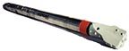
Bottom-hole Assemblies
Drilling curved and horizontal boreholes requires specialized drilling equipment. The specialized drilling equipment is contained in a bottom-hole assembly that consists of a drilling tool, a bent sub-assembly and a guidance tool. The drilling tool is oriented preferentially in the borehole by the bent sub-assembly in order to drill in the desired direction. The guidance tool supplies drilling tool orientation and the azimuth and inclination of the borehole to the driller. There are three types of drilling tools used in directional drilling: the down hole mud motor, the jetting tool and the compaction tool.Down hole mud motors have the advantage of eliminating drill string rotation, thus making it possible to drill short radius of curvature boreholes. Down hole mud motors may be either positive displacement motors or turbodrills. Drilling fluid is pumped down the drill pipe into the cavities of the motor. The drilling fluid causes the motor, and therefore the drill bit, to turn. The speed of the mud motor is controlled with the drilling fluid pressure. Different types of drill bits can be attached to the motor to accommodate the drilling conditions.
Jetting tools use hydraulic pressure to cut the geologic formations and can be used in rotary drilling. The hydraulic jet is directed from a bent housing or from a drilling fluid port on a drill bit that is attached to a bent sub-assembly. The force of the hydraulic jet is controlled with the drilling fluid pump. To drill the curved section of borehole, the bent sub-assembly and the hydraulic jet are placed in the direction of the borehole deviation. The drill string is advanced by the force of the weight on the bit and with the hydraulic force of the drill rig. The drill string will follow the direction of the hydraulic jet. To drill a straight segment of borehole, the drill string is rotated. The rotation prevents the hydraulic jet from having a preferred orientation. Another method for drilling a straight segment of borehole calls for alternating the direction of the bent sub-assembly from one direction and its 180-degree opposite. The resulting borehole will have a sawtooth profile.
A compaction drilling tool works on the same principle as wood chisel. Compaction tools are wedge-shaped and move in the direction of the slant on the face of the wedge when the drill string is pushed into the geologic formation. The drill string is pushed when the borehole direction needs to be changed, and rotated and pushed when the borehole direction is to remain unchanged. Compaction tools generally are used in geologic conditions that are unconsolidated, and in small boreholes with limited vertical depth (< 50 feet). Water is used to help lubricate and cool the drilling tool, but drill cuttings or drilling fluid do not return to the surface. Compaction tools reduce formation permeability, as does drilling fluid, but drilling fluid can be removed during well development or it may be biodegraded.
The bent sub-assembly either can be a fixed-angle assembly or can be adjusted while drilling. The fixed-angle assemblies are used with down-hole mud motors, jetting and compaction drilling tools. A fixed-angle bent sub-assembly can be part of the down hole motor housing or jetting tool or can be a separate interchangeable part of the bottom-hole assembly. An adjustable-angle assembly is less common and is used with down hole mud motors.
The guidance system is located in the bottom-hole assembly behind the drilling tool and the bent sub-assembly. Types of guidance include: a magnetometer-accelerometer system, an inertial (gyroscope) system or a radio beacon-receiver system.
The magnetometer-accelerometer guidance system uses three magnetometers to measure the position (azimuth) of the tool in the earth's magnetic field and three accelerometers to measure the position (inclination) of the tool in the earth's gravitational field. The steering tool sends information to a computer at the surface where the tool azimuth, inclination and drilling tool orientation are calculated. The azimuth and inclination, along with the distance that the steering tool has penetrated into the borehole, allow the driller to calculate the position of the steering tool in the subsurface.
Some magnetometer-accelerometer guidance systems use a secondary survey system, which induces a known magnetic field at the ground surface. A computer program connected to both the surface magnetic field and the steering tool compares the magnetic field measured by the steering tool and the theoretical magnetic field at the steering tool. If there is a discrepancy between the actual and theoretical values, then the secondary survey may be repeated or the steering tool is removed and recalibrated.
The inertial guidance system is based on the same navigation principles as used in navigation systems in guided missiles and airplanes. The system uses three gyroscopes to measure the azimuth of the steering tool and three accelerometers to measure the inclination of the steering tool. The gyroscopes are aligned to True North at the ground surface before the survey is made. Any deviation from True North during the survey is detected by the gyroscopes and relayed to the surface where the azimuth, inclination and drilling tool orientation are calculated by a computer.
The radio beacon-receiver guidance system is a battery-operated system that sends a constant electro-magnetic signal from the bottom-hole assembly to a receiver in a surface unit. The surface unit then locates the position of the beacon and calculates the depth to the beacon. This method often is called the "walk over" method because the surface unit is walked over the beacon. The radio beacon-receiver guidance system is limited to applications with vertical depths less than approximately 40 feet. At depths greater than approximately 40 feet, the radio beacon is diffused and can no longer be accurately received by the surface unit.

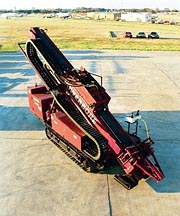
Drilling Rigs
Drilling rigs are built in small, medium and large sizes. Drilling companies that specialize in utility installation will own small- and medium-sized drilling rigs. Drilling companies that provide a river crossing service will own large drilling rigs and may also own medium and small rigs. All directional drilling rigs have a few common characteristics: a capacity for using a fluid while drilling and a method for providing a thrust force to the drill string to compensate for lost weight on the bit when drilling the horizontal section of a borehole.Small drilling rigs are mounted on a trailer, truck or a self-propelled, tracked vehicle. The drilling fluid system is limited; water or a dilute, bentonite-based fluid are the common drilling fluids. The maximum thrust force provided to the drill string is less than 40,000 pounds. These drilling rigs are used to install utilities beneath roads and subdivisions in continuous boreholes and offer a limited range of horizontal-well installation capabilities. Horizontal well installations generally are limited to small diameter pipes (4-inch outside diameter [OD]) at vertical depths of less than 30 feet in semi-consolidated sediments.
Medium-size drilling rigs are mounted on a trailer or a self-propelled, tracked vehicle. The drilling fluid systems are more sophisticated than those on small drilling rigs and can accommodate all types of drilling fluids. The maximum thrust force provided to the drill string generally is less than 80,000 pounds. These drilling rigs are used to install utilities beneath roads, subdivisions and small rivers. Horizontal well installations can be in continuous or blind boreholes with pipes less than or equal to 8 inches (OD).
Large drilling rigs are mounted on trailers. The drilling fluid systems are sophisticated and can accommodate all types of drilling fluids. The maximum thrust force provided to the drill string generally is less than 800,000 pounds. Horizontal well installations can be in continuous or blind boreholes with large diameter pipes (<14-inch OD).
Report Abusive Comment