Meeting Variable Loads
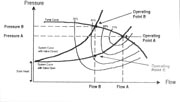
Pumping system designers, engineers and contractors constantly face the challenge of meeting a varying load with a fixed-capacity pump. Pumps are sized to meet the maximum foreseeable load, but that maximum load only may occur a small percentage of the time. The application might be in a household with loads varying from drip irrigation in the garden to light household usage to lawn watering to a back-up fire system. Or, it could be a golf course with zones having widely varying flow requirements. You would hope, though, that the golf course irrigation system designer had put some effort into balancing the loads.Two months ago, this column focused on constant pressure systems and on the control valve solution to dealing with varying flow demand. A control valve can be used to automatically throttle back the excess flow and maintain a constant pressure on the demand side of the valve. As the control valve reduces system flow, the pressure on the pump side of the valve goes up, following the pump curve, and the operating point moves to the left. Figure 1 shows a generic pump curve and two system curves with the corresponding operating points - “A” for the control valve in the open position, and “B” when the valve is in the throttle position. The system curves depict the static head, plus the friction losses in the piping system, including those of the control valve.As we move toward the left side of the curve, the horsepower required to run the pump drops. This may be counter-intuitive to some, but the fact is that most of a pump's energy goes into producing flow, not pressure. Figure 2 is the pump curve for a 3-HP pump and includes a shaft power curve. Notice that, as the flow is reduced, the horsepower required to run the pump drops dramatically. At 90 gpm, it takes 3 ½ HP to run this pump, and at 20 gpm, only about half that amount. This is the order of magnitude of energy savings that can be realized using a throttling valve.
VFDs, on the other hand, move the operating point straight down the system curve to operating point “C” on Figure 1. How is horsepower affected? To answer this question we turn to the affinity laws.
The Affinity Laws
The affinity laws describe what happens when the speed of a centrifugal pump changes. (The same laws apply to changing impeller sizes in a particular pump. Just substitute impeller diameter for motor speed.)
1. Flow (F) is directly proportional to motor speed (S) - S1/S2= F1/F2.
2. Pressure (P) is proportional to the square of the speed - (S1/S2)2 = P1/P2
3. HP is proportional to the cube of the speed - (S1/S2)3 = HP1/HP2
For example, let's say we have a 100-HP pump, pumping 1,000 gpm at 100 psi at 3,450 rpm. If we cut the speed in half to 1,725 rpm, the flow rate will drop to 500 gpm, the pressure to 25 psi and the HP to 12.5.

Operating Cost
Much is made of the energy savings potential of VFD systems. It is easy to generalize about cost savings when comparing a VFD system to conventional constant speed pumping systems and to systems utilizing a throttling valve. Just look at the 100-HP example above where cutting the flow in half cut the horsepower by 87.5 percent. Even after you factor out the drive's 3-percent operating efficiency loss, you still have a substantial energy savings. Compare that to the earlier example in Figure 2, where using a throttling valve, a reduction of 75 percent in the flow yielded a 50 percent drop in HP. So, why isn't everyone using a VFD? Here are a few reasons:1. Not enough pressure - The second affinity law states that the pressure drops as the square of the speed. If you need most of the pressure your pump produces most of the time, you can't use a VFD. If, on the other hand, your load varies from a low-pressure, low-flow drip system to a high-pressure, high-flow fire system, perhaps you should consider a VFD.
2. Turn-down ratio - This is the ratio of the maximum versus minimum flow rates your system needs to provide. A ratio of 4:1 is typical for VFDs. For submersible motors, Franklin Electric recommends 2:1 and motor cooling may be a factor at lower flow rates. If you need to throttle your system more than these ratios, go with a valve.
3. Environmental conditions - VFDs use computers and computers don't like high ambient temperatures. You may need to add an AC cooling system, so factor in some added cost. Also figure in some filtration if you are in a dusty environment.
4. Pump cable length and harmonics - Most VFDs have a limit on the length of power cable between the drive and the motor. This may be a factor for submersible applications. Also, make sure you discuss the existence of any harmonics and other electrical noise associated with your drive and the effect on nearby electronic equipment.
Other functions provided by VFDs include control of the motor acceleration and deceleration, torque control, and motor protection. In pumping applications, the motor acceleration normally is controlled, often in several steps. With a submersible pump, it is important to accelerate to at least half speed within one second for motor bearing lubrication, then accelerate to the desired speed in another 10 seconds or so. Deceleration, on the other hand, is left to nature in a pumping application, unless water hammer is a factor. As to motor protection, modern VFDs include phase loss and balance protection, high voltage protection and current protection. It usually is not necessary to provide additional motor protection when employing a VFD, but many system designers do it just the same, believing that you never can have too much protection.
We have covered most of the basic concepts having to do with variable frequency drives in these last two articles. Next month, we will conclude our series on VFDs with a close look at applications.
'Til then ….
ND


Report Abusive Comment