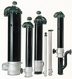
Figure 1. Pitless units.
One of the most important aspects of installing a water well system is to provide a method of protecting the wellhead so that surface water, debris, insects and vermin do not enter the well. There are two primary methods used to provide wellhead protection.
The two methods differ in the way the discharge pipe exits the well. The first method uses a pitless unit or pitless adapter and a well cap, and is used when the discharge exits the well casing underground, below the frost line. The second uses a sanitary well seal, and the discharge pipe exits the well straight out of the top, aboveground. It follows that if you need to provide freeze protection at the wellhead, use the pitless method, and if you don't, use a well seal.
Pitless units and adapters are so named because they allow the discharge-pipe connection to be made below the frost line without having the well casing terminate in a pit, thus the term “pitless.” The difference between a pitless unit and a pitless adapter is that a pitless unit includes a short section of well casing, which is connected to the top of the primary well casing (see Figure 1). A pitless adapter, on the other hand, uses the primary well casing as its housing (see Figure 2). Both allow for the easy removal of the pump because the connection between the drop pipe and the side outlet slides apart as the pump is hoisted out of the well.
Pitless units are much larger and stronger than pitless adapters and, therefore, are used in most large or deep wells where a considerable amount of weight must be supported. Pitless adapters, on the other hand, are used in most residential wells where there is less weight to be supported, because they are less expensive and easier to install. If you are installing a fairly deep pump on steel drop pipe, though, make sure to check the specs on your pitless adapter to make sure it will support the weight.
A pitless adapter will support 200 feet to 600 feet of steel well casing, depending on the type and design. A well-designed pitless unit will support more weight than the pipe threads, which will fail before the pitless unit fails. Whether using a pitless unit or pitless adapter, check with the pitless manufacturer to make sure that it will support the weight of your drop pipe, pump cable, column of water and pump.

Figure 2. Pitless adapter.
Installation
I will not go through a step-by-step installation procedure in this article because most pitless manufacturers include very good installation instructions with their products. However, a brief installation overview seems appropriate to give you a sense of what is required to accomplish this part of a pumped water-system installation.First of all, the earth around the wellhead must be excavated to below the frost line to facilitate installation of both pitless types. Pitless units are connected to the well casing by welding, threading or with a compression connection. They must be ordered with the specific size and type of connections needed to mate up with the well casing and outlet piping on your particular job.
Pitless adapters are installed by drilling or cutting a hole in the side of the well casing, and by attaching the stationary part of the adapter to the hole by welding, threading or clamping. The movable part of the pitless adapter is threaded onto the top of the drop pipe, and is attached to the stationary part by sliding it into a slot or hole. O-ring seals are used to provide a watertight joint.
Well caps are an important part of all pitless systems. They provide the required seal at the wellhead, as well as a means of getting the pump cable out of the well, and of venting the well (see Figure 3). They should be carefully selected to provide the type of protection needed for the particular well at hand. If the well is in a floodplain, a watertight cap should be used. Otherwise, a less expensive ventilated cap can be used.
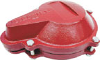
Figure 3. Watertight well cap.
Well Seals
If you install pumps in an area where freezing is not a problem, a well seal can be used (see Figure 4). Well seals are easy to install, inexpensive and provide excellent wellhead protection when properly installed. They consist of a top plate and bottom plate made of steel, cast iron or plastic, and a packer made of rubber or soft plastic. The top plate is larger than the outside diameter of the well casing, and the packer and bottom plate are sized to fit the inside of the well casing. The two plates are held together with bolts, which squeeze the packer when tightened, forcing it against the inside of the well casing, creating a watertight seal.Besides the bolt holes, well seals have three or four holes for the drop pipe (or twin pipes in a jet pump system), the pump cable and the vent. A seal for 8-inch well casing and 11⁄4-inch drop pipe would be ordered as an 8-by-11⁄4. Your choice of steel, cast iron or plastic will depend on the load to be supported, local codes and what is popular and available in your area. Make sure to accurately calculate the weight of the drop pipe, pump, pump cable and water column, to make sure the well seal will support the load. This particularly is important when using cast iron, cast aluminum or plastic well seals, because they do not have the load-carrying capacity of seals made from steel plate.
Installing a well seal is a simple matter:
- Slip the seal down over the drop pipe while supporting the drop-pipe string with a pipe holder.
- Run the pump cable through the wire hole into conduit or a J-Box.
- Screw the branch side of a pipe tee onto the drop pipe.
- Lower the string until the tee is down on the seal and the seal is seated on the well casing.
- Tighten the bolts to squeeze the packer against the inside of the well casing.
- Install a plug in the top of the tee, and you are done.

Figure 4. Well seal.
Local Codes
Before installing any type of wellhead protection, check your local codes to see if there are any particular requirements that must be met. Some states are very specific about the types of well caps and seals that can and cannot be installed. Others require that the wellhead terminate a minimum number of inches above the ground. Code compliance in the wellhead area is one of the most important aspects of a properly completed well.By paying careful attention to the codes, the choice of components and the installation, you can be assured of providing your customer with a safe and sanitary well.
Next month, we will talk about the portion of the system between the wellhead and the pressure tank. 'Til then ….
P.S.
David Bumbalough from Franklin Electric e-mailed me regarding my October article on pump cable splicing. He pointed out that I failed to stress the importance of cleaning the pump cable surfaces adjacent to the splice, and said that he has seen many failed splices that resulted from improper cleaning. Thank you, David, for bringing up a good point.ND

Report Abusive Comment