The Disconnect - The first component in any pumped water system is the disconnect (see Figure 1).
The National Electrical Code (NEC) states that every motor circuit shall have a disconnect located within sight of, but not more than 50 feet from, the motor control, unless it can be locked in the off-position. This is to protect the service technician from being shocked by someone inadvertently turning on the power while work is being done on the motor controls. If the disconnect is in sight, the technician can keep an eye on it, but it still is a good idea to keep it locked in the off-position while servicing the system.
The NEC also requires that each motor circuit have a separate fuse or circuit breaker. If time-delayed fuses are used, they are sized at not more than 175 percent of motor full-load amps, and a thermal-magnetic circuit breaker is sized at not more than 250 percent of the motor full-load amps.
The Pump Switch - Next in line is the pump-switching device. In a system with a pressure tank, this will be a pressure switch. It senses the pressure in the system, turning on the pump when the pressure drops below the turn-on threshold and turning off the pump when the pressure exceeds the turn-off point. In a system with an open storage tank, you will use float switches or an electronic liquid level control to start and stop the well pump.
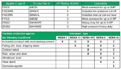
Which Pressure Switch - If you have worked with pumps, you know there are a number of choices available to you in pressure switches. Two manufacturers of commonly used switches are Square D and Furnas. Both companies make a host of excellent products. The table on page 18 shows the models that normally are encountered in a residential pumped water system. The models listed are available in several preset cut-in and differential settings, and both settings can be easily adjusted as needed.

Pressure Switches
Choose a switch with a horsepower rating high enough to handle the load in your system. Ninety percent of the residential systems you are likely to encounter will use the FSG2 or 69ESI switches. They can handle up to 2 HP directly, and any horsepower in conjunction with a motor starter. Also make sure the switch you use is rated for the voltage you are switching. The smaller switches are not rated for 460 volts because their contacts will not handle the arcing inherent at the higher voltages.Basic Dry Well Protections - The second set of switches on the list, the M4 and 69WEC, have a low-pressure cut-off. This is the simplest and least expensive option to provide protection from loss of flow. The low-pressure cut-off turns off the pump when the pressure in the system drops 10 psi below the cut-in pressure in the M4, and to 6 psi in the 69WEC. This provides a basic level of protection preventing the pump and motor from being damaged by flow problems. However, this type of protection is not foolproof. It will not shut off the pump if the flow stops during the fill cycle when the system pressure is between the cut-in and cut-out settings. If you are in an area where there is more than a remote likelihood of the well running dry, or something else happening to slow or stop the flow from the pump, you will be better to choose an electronic pump protector. Next month, we will discuss pump protection in detail.
Motor Starters - When installing a pump with a single-phase motor larger than 3 HP, you need a motor starter. A motor starter simply is a large relay with contacts rated to handle the current drawn by the motor. If you are using a Franklin motor, their control boxes are motor starters sized to the motor HP.
Enclosures - Whether your electrical equipment is mounted indoors or out, it should be protected by the right enclosure. The National Electrical Manufacturers Association (NEMA) has designed certain types of enclosures for different applications. The types you will encounter in water systems are as follows.

NEMA-rated Enclosures
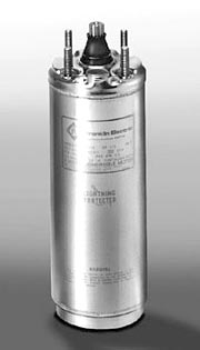
Two-wire and Three-wire Pumps -A question you likely will be asked when ordering a pump is whether you want a two- or three-wire motor. Single-phase motors have an extra set of windings, which are energized for a split second during start-up to provide extra torque to help get them spinning. These windings are called the start windings. To help the start windings do their thing, an electrical device is employed in the start circuit. In a three-wire motor, this device is called a start capacitor and is located in a control box, usually mounted aboveground, near the pressure tank. To get separate power from the start capacitor to the start windings in the motor requires a third wire, thus the designation “three-wire capacitor-start motor.”Two-wire motors (at least those made by Franklin Electric, which makes most of the submersible motors used in North America) are called split-phase motors and do not require a capacitor in the start circuit. Instead, they have a Bi-metal/triac switch in the motor housing, which provides full power to the start windings for approximately one-third of a second on start-up. Thus, only two wires (plus a ground) are required between the power source and the motor.
Franklin two-wire motors are available from 1⁄3 HP to 11⁄2 HP. Franklin three-wire motors are available from 1⁄3 HP to 15 HP. Three-wire motors from 1⁄3 HP to 1 HP are capacitor-start, induction-run motors, and from 11⁄2 HP to 15 HP, they are capacitor-start, capacitor-run motors.
The choice of two-wire or three-wire motors strictly is a matter of personal preference. A little more than half of the motors sold in the U.S. are three-wire motors. Both have their advantages and disadvantages. In some parts of the country, you could not give away a three-wire motor, and the same is true for two-wire motors in other regions. Check with your local distributor to see what other contractors are using in your area, because that is what will be most readily available at the best price.
Although the terms “two-wire” and “three-wire” still are widely used as described above, submersible motors actually now have three wires and four wires, respectively. The manufacturers are required by code to supply them with a ground wire in the pigtail. So, when we say a two- or three-wire motor, we are talking about the two- or three-current carrying wires.
And finally, all of the wiring from the disconnect to the well head should be sized properly to handle the amount of current drawn by the motor and designed for the application. The aboveground portion of the wiring should be in conduit, according to the codes in effect in your area, and any buried wire should be the Type UF. Once again, make sure you follow manufacturer's wire sizing charts and local codes for compliance.
Next month, we will explore single-phase pump and motor protection techniques and devices. 'Til then ... .
ND
Report Abusive Comment