The usual role of a deep foundation is to transfer vertical load through weak, near-surface soils to rock or strong soil at depth. Shallow foundations, on the other hand, frequently are used when the surface soils are capable of supporting load without excessive settlement.
There are many types of deep foundations, and classification can be done in various ways. Several of the factors that can be used in classifying deep foundations:
- Materials: Steel; concrete - plain, reinforced or pre-stressed; timber; or some combination of these materials.
- Methods of transferring load to the soil or rock: Principally in end-bearing, principally in skin friction or in some combination of the two methods.
- Influence of installation on soil or rock: Displacement piles, such as a closed-ended steel pipe, that displace a large volume of soil as the piles are driven; or non-displacement piles, such as H-pile or open-ended steel pipe, that displace a relatively small volume of soil during driving (until the pipe becomes plugged), or drilled shafts, which result in essentially no displacement of the soil or rock.
- Method of installation: Impact-hammers - hydraulic-, air- or steam-powered, or diesel; vibratory hammers; drilling an open hole; or by some special method.
Thus an example of a type of deep foundation is a structural-steel shape (essentially non-displacement), driven by a diesel hammer to rock, which carries its load in end-bearing. The drilled shaft normally is used as a deep foundation, but it also can be used as a shallow foundation.
In a Nutshell
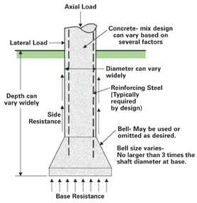
A drilled shaft is a deep foundation that is constructed by placing fluid concrete in a drilled hole. Reinforcing steel can be installed in the excavation, if desired, prior to placing the concrete. A schematic example of a typical drilled shaft is shown. The arrows indicate that drilled shafts can carry both axial and lateral loads.The drilled shaft commonly is constructed by employing rotary drilling equipment to bore a cylindrical hole. The borehole may remain unsupported in soils with cohesion or in rock, or it may be kept open by using drilling slurry or casing in granular or bouldery soils, occasionally in highly jointed cohesive soil or rock or in very soft cohesive soil. The casing usually is temporary. It can be placed in a number of ways. After the cylindrical hole is excavated and the casing placed, if necessary, an underreaming tool can be used, if desired, to enlarge the base of a drilled shaft in cohesive soil. A rebar cage can be placed, if needed from a design perspective, and the excavation is filled with fresh concrete. The temporary casing is recovered.
Drilled shafts also may be constructed by the percussion method of excavation. In this case, surface casing is set and the soil or rock is excavated by a grab bucket, or clamshell. In hard soil or rock, a rock breaker or similar tool can be employed to break the rock before excavation. A rock breaker consists of a heavy bar with a chisel-like tip or a heavy implement shaped like a star that is dropped repeatedly to fracture the hard soil or rock. An alternate method is to use a hammergrab, a heavy bucket with a sharp point that, when dropped, will penetrate the geomaterial and can then be used to excavate it without removing the tool and changing to a clamshell.
The borehole for the drilled shaft can be excavated by percussion to make excavations with non-circular cross sections. A surface casing, or guide, in the form of a cross or a rectangle can be placed. The transverse dimensions of the guide will conform to the size of the grab bucket. A drilled shaft of this type is called a “barrette.” Barrettes have had little use in the United States during the recent past, except that slurry walls have been excavated with the identical method used to excavate the barrette.
Some deep foundations that are not classified as drilled shafts also involve the placing of concrete in a preformed hole:
- The pressure-injected footing is constructed, normally in granular soils, by placing a casing and excavating the interior soil, by placing a quantity of dry-mix concrete in the bottom of the casing, and dropping a weight on the concrete. The impact causes the granular soil to be compacted and, as more dry-mix cement is added, a bulb is formed. The process is continued as the casing gradually is retrieved. The completed foundation consists of a nearly cylindrical shaft with an enlarged base.
- The step-taper pile and similar types of cast-in-place piles are constructed by driving a thin, steel shell into place through the use of a mandrel. The mandrel is withdrawn and then the shell is filled with concrete.
- The auger-placed-grout pile is constructed by rotating a continuous-flight auger into place. The auger has a hollow stem through which grout is forced under pressure. The auger gradually is withdrawn and the grout - or special concrete - fills the space formerly occupied by the auger.
It is important to recognize that these and similar types of foundations, while having some characteristics of drilled shafts, are, in fact, not drilled shafts and should not be designed as such.

A Brief History
The construction of higher and heavier buildings in major northern urban areas, where the subsurface conditions consisted of relatively thick layers of medium-to-soft clays overlying deep glacial till or bedrock, led to the development of the earliest versions of the drilled shaft foundation. For example, in the late nineteenth century, hand-dug “Chicago” and “Gow” caissons were excavated to a hardpan layer to act as a type of deep footing. These foundations were constructed by making the excavation and by placing sections of permanent liners to retain the soil (wood lagging or metal sheets) by hand. Early designs specified bearing pressures for the hardpan that usually were very conservative - around 8,000 psf.Machine excavation soon superseded the hand-dug caissons. An early power-driven auger, built around 1908, was capable of boring a 12-inch hole to a depth of 20 feet to 40 feet. Records from 1920 describe horse-driven rotary machines being used to auger boreholes for drilled shafts in Texas for shafts 25 feet or more in depth. Early development of drilled shafts in the San Antonio area was motivated by very different subsurface conditions than the northern urban regions. The surface soils generally are strong, but highly expansive, and drilled shafts were used to carry loads below the expansive surficial soils.
In 1931, Hugh Williams of Dallas started to build machines for excavating shallow holes and later manufactured truck-mounted machines. His machine became popular in the drilled shaft industry and versions still are used today.
Prior to World War II, the development of large-scale mobile, auger-type and bucket-type, earth-drilling equipment allowed more economical and faster construction of the drilled-shaft foundation. In the late 1940s and early 1950s, drilling contractors continued to introduce techniques for larger underreams and for cutting in rock. Large-diameter, straight shafts founded entirely in clay and deriving most of their support from side resistance came into common usage in Britain. Many contractors found that by introducing casing and drilling mud into boreholes, a process long established by the oil industry, boreholes could be cut through permeable soils below the water table and in caving soils economically.
Stabilization of the borehole also has been accomplished by injection of grouts, by dewatering and by freezing of the soil. These techniques can be expensive and usually are not required.
The first planned use of drilled shafts on a state department of transportation project is believed to have been a bridge project in the San Angelo district of Texas in 1950. By the early 1970s, drilled shafts became the foundation of choice in coastal locations in Texas.
The development of drilled shafts, more or les independently, in various parts of the world led to different terminologies. “Drilled shaft” is the term first used in Texas, while “drilled caisson” or “drilled pier” is more common in the midwestern United States. “Cast-in-drilled-hole pile” is a term that's used in California by CalTrans, and “bored pile” is common outside of the United States. These terms all describe essentially the same type of foundation. Many contractors prefer not to refer to drilled shafts as “caissons,” as that term is considered descriptive of foundations excavated by hand in pneumatic chambers, which are not drilled shafts.
While the construction technology advanced rapidly after World War II, the development of theories for design and analytical techniques lagged behind. In the late 1950s and early 1960s, computers, analytical methods and full-scale load-testing programs began to produce a better understanding of drilled shaft behavior. Marked differences between the behavior of driven piles and drilled shafts were noted, and the importance of proper quality control and inspection was realized. Extensive research was carried on through the 1960s and into the 1980s, and improved design methods and construction procedures were developed such that drilled shafts became regarded as a reliable foundation system for highway structures by numerous state DOTs. Since that time, intensive research has continued, much of it sponsored by state DOTs, the Federal Highway Administration (FHWA) and the Electric Power Research Institute. A great deal of this research has focused on collection and analysis of large databases of full-scale tests, development of expedient methods for performing loading tests, improvements in methods for characterizing uncertainty in the prediction of resistance and settlement, adaptations of principles of rock mechanics to drilled shaft design, and improvement of procedures for evaluating the structural integrity of drilled shafts.
In 1977, a set of design manuals for drilled shafts was first published by the FHWA - based on experience at the time. A new design manual was published by the FHWA in 1988, emphasizing construction procedures and simple, conservative design methods. The manual was updated again in 1999 to update both design procedures and descriptions of construction technology.
ND
Report Abusive Comment