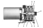
Figure 1.
Before getting into this month’s topic, I want to respond to a comment from a reader regarding my December 2006 pump article, titled “Plumbing the Pressure Tank.” In that article, I recommended installing a check valve between the pressure tank and the wellhead to supplement the well check valve(s) in preventing the water in the pressure tank from draining back into the well when the pump was not running. The reader pointed out that sanitary protection should be our number one concern, and that no belowground potable water line should ever be subjected to a vacuum. With a check valve at the tank, a leak in the drop pipe or any of the in-well check valves would create a vacuum condition that potentially could draw contaminated surface water into the well through a pin hole in the section between the wellhead and the tank. He makes a very good point, and I therefore withdraw my recommendation to install a check valve between the pressure tank and the wellhead. I appreciate the reader’s taking the time to make his point. Keep those comments coming.
Last month, we began this discussion about pumped water systems with a look at the four basic types of pumps that are used – the straight centrifugal, the shallow well jet pump, the deep well jet pump and the submersible pump. We also described the two major components of a water system pump, the impeller and the diffuser (sometimes called the volute). Let us now look more closely at these two components to see how they can be manipulated to affect a pump’s performance.
Water Pressure
While the speed and diameter of the impeller are the primary determinants of a pump’s pressure capability, these factors may be limited by other considerations. For instance, for a submersible pump to fit into a 4-inch well, the impellers must be less than 4 inches in diameter. Therefore, we do not have the option of increasing the diameter of the impeller in a 4-inch pump to increase its pressure output. Additionally, the speed at which an impeller turns is limited to the speed of the motor that drives it. Since we primarily are dealing with electrically driven pumps in ground water systems, we are limited by the speed of the electric motors, which, at 60 Hz, is 3,450 rpm for a two-pole motor. This limitation can be exceeded by increasing the 60-Hz frequency through the use of a variable frequency drive (VFD), as will be discussed in a later article. For our purposes in this basic discussion, let’s assume we are stuck with 60 Hz.A simple way to increase pressure is to stack pumps, hooking them in series, with the outlet of the first connected to the inlet of the second. When stacking pumps, each one adds its pressure capability to that of the one before it, so the total pressure capability of the stack is the sum of the pressures of all the pumps. This was a common practice before multi-stage centrifugal pumps became readily available. A multi-stage pump has more than one impeller/diffuser set (a stage) in one housing, driven by a single motor (see Figure 1).
Submersible pumps, with the exception of single-stage turbines, are multi-stage pumps (see Figure 2 at right). Each stage in a multi-stage pump adds its own pressure capability to the stage before it. Each stage of a 4-inch submersible pump, running at 3,450 rpm with a single 3.5-inch-diameter impeller, will produce about 8 psi of discharge pressure at its design flow rate.
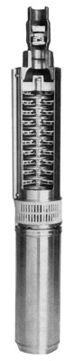
Figure 2.
How to Figure the Pressure Needed
Consider a pump set 36 feet down in a well with a pumping level (the distance from ground level to the water level in the well with the pump running) at 16 feet. The first 20 feet up from the pump to the top of the water in the well is taken care of by atmospheric pressure (more on this next month). The pump must lift the water from the pumping level to the point of use. Let’s say we are just filling a watering trough, so the total lift would be 16 feet, plus another 2 feet to get it over the lip of the trough or about 18 feet. To convert from PSI to feet of lift, multiply by 2.31. Therefore, an 8-psi single-stage pump will lift the water in this well 18.5 feet (8 psi times 2.31) – just enough pressure for filling a watering trough.But let’s say we want to be able to take a shower in the upstairs bathroom, 24 feet above the ground. We will need enough pressure to lift the water from the pumping level in the well to the showerhead, plus another 15 pounds to 20 pounds to create a nice shower. Adding it up, that’s 16 feet to the surface, plus 24 feet to the showerhead, totaling 40 feet of lift. Divide 40 feet by 2.31 feet per PSI gives us 17.3 psi. Now, add the 20 psi we need for a nice shower, and we’ll need a total of 37.3 psi to do the job. Adding four more impeller stages will increase the pressure capability of this pump to 40 psi (five total stages times 8 psi per stage equals 40 psi - Voilà!).
What about the pressure capability of larger pumps? As we have said, each stage of a 4-inch submersible pump, running at 3,450 rpm, will increase pressure about 8 psi, which is equal to 18 feet of lift. Each stage of a 6-inch submersible pump produces about 25 psi, or about 60 feet of lift at 3,450 rpm.
Flow Capacity
The amount of water pumped by a centrifugal pump is determined by the RPM of the pump and the width of the impeller. The only major difference between the impellers in a 5-gpm, 4-inch submersible and those of a 75-gpm, 4-inch submersible is the width of the impellers. Both are the same nominal diameter, because they both must fit into a 4-inch well. Of course, the 75-gpm sub will require a much larger motor to do the additional work of pumping more water.By the same token, a 5-gpm pump designed to pump from a 200-foot pumping level might have 10 or 12 stages, and a 1⁄2-HP motor, whereas a 5-gpm pump for a well with a water level at 800 feet would need at least 40 stages and perhaps a 3-HP motor. The more work to be done, the more horsepower required.
Next month, we will take a close look at how centrifugal pumps actually lift water. ’Til then ….
ND


Report Abusive Comment