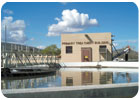
Wastewater treatment plants can pose a significant threat to local ground water.
The installation of ground water monitoring wells at wastewater treatment facilities may be essential when such facilities have the potential for degrading the area’s ground water quality. Discharge to ground water at these facilities is caused by seepage or direct discharge of effluent through the soil profile. The necessity for monitoring wells and/or ground water discharge plans is based on a number of factors, including the soil type, depth to ground water, strength of the waste, mobility of the waste, and general quality of the ground water. If the potential for ground water degradation is high, monitoring wells are necessary to ensure that these discharges are not degrading the ground water quality beyond the ground water quality standards, especially when they are in close proximity to water supplies and other facilities that can be impacted by ground water contamination.
Location and Number
A minimum of three monitoring wells must be installed to determine ground water flow direction. One well should be located in an area upgradient of the facility, with two located downgradient. However, the number of monitoring wells also will depend on the size of the facility. The downgradient wells should not be spaced more than 500 feet apart, and should not be located more than 200 feet outside of the site perimeter.Diameter
Monitoring wells can be constructed of casing and screen materials that are a minimum of 2 inches inside diameter. The borehole into which the monitoring well is to be installed should be a minimum of 4 inches greater in diameter than the casing (i.e., a 2-inch well must be installed in a 6-inch borehole).Casing and Screen Material
If PVC is selected for well construction, only those materials that meet or exceed the National Sanitation Foundation (NSF) Standard 14 must be used. Rigid PVC materials used for casing and well screen that meet or exceed NSF Standard 14 essentially are free of plasticizers. All casing and screen must be supplied with threaded flush joints or threaded couplers, PVC casing and screen must not have glue joints. The well casing should extend 2 feet above the ground surface when the well is completed.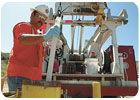
There are various methods of well development.
Length, Depth and Packing
The monitoring well(s) must be drilled to a depth that will monitor the first water encountered. The well screen should extend 5 feet to 15 feet into the water table, with sufficient screen above the water table to detect any substances less dense than water. The well screen length should be based on water table fluctuations and other site conditions (such as confining layers). The well screen must be installed into a stable borehole. If the borehole tends to cave in or “blowout,” steps must be taken to stabilize the hole prior to screen installation.The screen gravel-pack must be composed of pre-washed, uniform (graded) quartz sand. The size of the gravel-pack chosen must be compatible with the slot size of the well screen. For natural-packed wells (no gravel-pack), where relatively homogeneous, coarse materials predominate, the screen slot size must be compatible with the formation.
Placement of the gravel-pack should be done carefully to avoid bridging in the borehole and to allow uniform settling around the screen. A tremie pipe can be used to guide the sand to the bottom of the hole and around the screen. If the well is shallow, the sand can be poured from the surface. The gravel pack must extend a minimum of 1 foot to 2 feet above the top of the screen. Field measurements should be taken to confirm the gravel-pack has reached this level prior to grouting.
Monitoring wells are key to subsurface environmental sampling to determine the presence and extent of any contamination.
Sealing Procedures
The seal used directly above the gravel-pack should be of bentonite – in the pelletized form. Enough pelletized bentonite should be added so that a seal 2 feet thick is formed directly above the gravel-pack. If no water is present in the borehole where the pellets were installed, water from a potable source must be added to fully expand the pellets. If it is not possible to install the bentonite seal as described above, an alternate procedure of installing the seal via tremie pipe may be used. The seal must be composed of pure bentonite and mixed with potable water. The bentonite mixture should be thick enough to provide an adequate seal while remaining pliable enough to be pumped.The annular space remaining above the seal must be grouted. The grout mixture should be composed of Portland cement and powdered bentonite. The grout mixture proportions must be 6 gallons of water to one 94-pound sack of cement. Two pounds of powdered bentonite should be added per sack of cement to control grout shrinkage. The grout must be thoroughly mixed until a consistent slurry is reached throughout. Under no circumstances should the grout be added to the well annulus dry.
Grout must be injected via tremie pipe immediately above the bentonite seal that was placed above the well screen. All hoses, pipes, tubes, water swivels, drill rods or passageways through which the grout is to be pumped should have an inside diameter of at least 0.5 inches. Grout injection must continue until clean grout reaches the ground surface. The well must not be disturbed for at least 48 hours after grouting to allow the grout time to set up.

Downgradient wells should not be spaced more than 500 feet apart.
Well Development
All monitoring wells must be developed to produce representative formation water. Representative formation water is assumed to have been obtained when pH, temperature and conductivity readings are stable, the water is turbid-free, and the minimum periods of development have been reached.Submersible pumps include centrifugal or positive displacement-type pumps, which are operated under submergence. If a submersible pump is utilized for well development, it must be of a type and capacity such that it can pump water from the well continuously for a period of at least five minutes without shutting off. Backpressure or other methods may be utilized to accomplish the desired pumping rate. The pump must be capable of being turned off and on instantaneously to create a surge in the well. When using a submersible pump, it is recommended the well be developed for a minimum of four hours.
A bladder or diaphragm pump is the type of pump that operates under the cycling of compressed air. The compressed air cycling inflates and deflates a diaphragm, which creates a pumping action. Bladder pumps capable of well development must pump a minimum of 2 gallons per minute continuously when installed in the well. Development with a bladder pump should be done for a minimum of eight hours.
A jet pump utilizes the Venturi principle to create sub-atmospheric pressure, which allows a suction pump to be utilized below a depth at which suction alone would not normally lift water. Jet pumps capable of well development must pump a minimum of 3 gallons per minute continuously when installed in the well. The recommended development time with a jet pump is four hours.
Suction pumps cannot be used in deeper than 25 feet. Suction pumps used to develop wells less than 25 feet deep must be capable of pumping at least 5 gallons per minute continuously without pumping the well dry in less than five minutes. The recommended minimum development time with a suction pump is four hours.
Bailers used in well development must be constructed of Teflon, stainless steel or PVC. Bailers must have a lower check valve, and be lowered into the well with non-water-absorbing cable. Wells developed using a bailer must be bailed until a turbid-free discharge is attained. If the well has insufficient recharge to permit continuous bailing, then the well should be bailed dry and allowed to fully recharge. This cycle should be repeated five times or until a turbid-free discharge is attained.
Compressed air supplied by an engine-driven compressor equipped with an oil trap may be used, provided the source of compressed air is capable of evacuating 50 percent of the water column from the well once every minute. The recommended well development time for compressed air is four hours, with cycling at two-minute intervals.
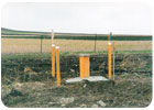
Security
All monitoring wells must be fitted with an outer protective casing. This protective casing must be constructed of steel, and be supplied with a steel locking cap. The steel casing must be securely set in cement and should extend a minimum of 2 inches above the top of the monitoring well casing. As additional protection, it is recommended that three posts be installed around each monitoring well. The posts should be constructed of 5-inch steel casing, and extend a minimum of 2 feet into the ground with 3 feet above ground. Each post should be filled and grouted in place with concrete.ND
This article is provided through the courtesy of the South Dakota Department of Environment & Natural Resources.
Report Abusive Comment