Editor’s note: This article is provided through the courtesy of Lifewater Canada, a volunteer-driven organization that trains and equips the rural poor in Africa to drill water wells and build washrooms. It is excerpted from the group’s well construction tutorial, intended to facilitate drilling projects taking place in less-than-ideal conditions.
To keep loose sand and gravel from collapsing into the borehole, it is necessary to use well casing and screen. The screen supports the borehole walls while allowing water to enter the well; unslotted casing is placed above the screen to keep the rest of the borehole open and serve as a housing for pumping equipment. Because the well screen is such an important factor affecting the efficiency of a well, it sometimes is called the heart of the well.
Screen Design
Well screens should have as large a percentage of non-clogging slots as possible, be resistant to corrosion, have sufficient strength to resist collapse, be easily developed and prevent sand pumping. These characteristics are best met in commercial continuous-slot (wire wrap) screens consisting of a triangular-shaped wire wrapped around an array of rods. If these screens are available, conduct a sieve analysis on samples on the water-bearing formation, and select a slot size that will retain 40 percent to 60 percent of the material.While wire-wrap screen should be used whenever possible, it may be exorbitantly expensive and/or not available. Most Lifewater wells commonly are constructed using PVC casing and screen. Gray PVC pipe, which is available in most countries, is relatively cheap, corrosion-resistant, lightweight, easy to work with and chemically inert.
Slot Design: Using a hack saw, cut slots in the plastic casing which are as long and close together as possible. Slots should be spaced as close together as possible vertically and should extend about one-fifth the circumference of the pipe; there should be three even rows of slots extending up the pipe separated by three narrower rows of solid, uncut pipe (for strength).
Screen/Casing Diameter:Three-inch diameter casing and screen can easily be inserted into a 6-inch borehole, and allows creation of an effective 1.25-in-thick filter pack (especially important where the aquifer is composed of very fine materials). However, because 3-inch screen often is not available and has low total open area, carefully centered and filter-packed 4-inch screen most frequently is used. Larger-diameter screens make the filter pack ineffective and do not significantly increase well yield. For example, moving from a 4-inch screen to a 5-inch screen will increase yield by 3 percent or less.
Screen Length: For confined aquifers, 80 percent to 90 percent of the thickness of the water-bearing zone should be screened. Best results are obtained by centering the screen section in the aquifer. For unconfined aquifers, maximum specific capacity is obtained by using the longest screen possible, but more available drawdown results from using the shortest screen possible. These factors are optimized by screening the bottom 30 percent to 50 percent of the aquifer. One 20-foot length of screen often is adequate. In many tropical areas, successful wells can be constructed by drilling 5 feet into underlying rock, and placing a 10-foot screen that straddles the bedrock/overburden interface.
Bottom Casing: Significant quantities of fine materials often are present in the extreme upper and lower parts of an aquifer. Therefore, unless the aquifer is less than 20 feet thick, extend the casing at least 3 feet to 6 feet into the top of the aquifer before starting the screen. Similarly, unless the aquifer is very thin, ensure that at least the bottom 3 feet to 6 feet of the aquifer is completed with a piece of solid casing pipe. This casing provides a place for solids to settle as they are drawn into the well, thus minimizing screen blockage and minimizing the amount of fines drawn into the well.
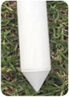
Bottom Plug: A plug, or drive shoe, always should be installed to help the casing slip down the borehole, and prevent unfiltered fines from entering the well. A cap or pointed wooden plug are the most common plugs. If belled casing is used, the non-belled end can be shaped into a point. Finally, a wash-down valve can be used or a one-way valve (allowing water to flow out of the casing) can be installed in a wooden plug that has a beveled inner surface. This valve allows the well to be effectively rinsed out, and ensures that the filter pack is effectively placed. If any type of wooden plug is used, it is good practice to place a cement plug at the bottom of the well to ensure that sediment cannot enter the well when the plug rots out. Put thick cement in thin plastic bags, drop them to the bottom of the well and then smash them open using drill pipe.
Drilling into Rock
No casing or screen generally is required in the portion of boreholes drilled into rock. The first 6 feet to 10 feet of the rock borehole should be 6 inches in diameter; the borehole then can be extended using a 4-inch bit (this maximizes the drilling speed which can be very slow in rock). The 4.5-inch OD casing should be placed into the 6-inch hole and carefully aligned with the hole. Fill the rock annular space with coarse gravel, followed by coarse sand/fine gravel with medium sand on top (this prevents fine sands and silts often found at the overburden-bedrock contact from moving into the well). Because the main water-bearing zone may be within the upper few inches of bedrock, only seal the casing into rock with cement where contamination is major concern.Centralizers
Whenever possible, centralizers should be used. Adding centralizers minimizes the chance of pump rods banging against the rising main during operation of the hand pump. Centralizers also are very important when installing casing because slots in the well screen may become severely blocked with clay if the screen rubs hard against the borehole wall while it is being inserted into the borehole. Centralizers also ensure that there is even distribution of cement grout and filter pack. Poor grout placement can result in contaminated surface water entering the well.These problems can be avoided by attaching (gluing, screwing, tying-on with wire) three centralizer strips to the top and bottom ends of the screen. Centralizers can be made from PVC casing, flexible green wood or half-inch-wide iron straps. Only fasten the lower end of each centralizer (so that it can flex), and do not put any on the casing or else the screen/casing may jam during placement.
Installation
Make sure you know the distance from the ground level to the bottom of the borehole, and ensure that the required lengths of well casing and screen are prepared, clean, close at hand and ready to install when the drilling is completed. Attach the casing sump with the drive shoe to the bottom of well screen. If bell-and-spigot pipe is not used, pre-glue a joining coupler (collar) to one end of each length of casing.Once the borehole is completed to the desired depth, continue to circulate drilling fluid through the drill pipe at the bottom of the borehole until the returning fluids are clear of cuttings, sand and clay balls. The fluid in the mud pits may need to be replaced several times before the water exiting the borehole is clean. When it is, keep the fluid circulating and the bit rotating, and slowly remove the drill pipe from the borehole.
When the drill pipe is removed, swing the engine/drive assembly to the side. Prepare to clamp the casing using two grip clamps formed from iron or wood. One clamp should be on the casing suspended in the hole, and the other on the length of casing to be joined. Alternatively, use a casing slip clamp made from -inch or 3⁄8-inch steel plate by cutting a slot slightly larger than the casing, and welding on a handle.
Keeping the borehole full of water, carefully lower the screen assembly into the borehole. Ensure that a grip clamp is attached, or use a slip clamp to catch the casing, should it slip while being lowered. One at a time, wipe clean, add and glue 20-foot lengths of casing. If a slip clamp is used, wrap a thin rope three or four times around the upper length of casing, and keep it tight when pulling the clamp back to ensure that the casing cannot slip. After the slip clamp is back in place, lessen the tension on the rope and allow the casing to slowly slip into the well until it is again resting on the clamp. Continue to add and lower casing until the well screen reaches the bottom of the borehole. Then raise it slightly and suspend it using grip clamps or by tying a rope to the drill table (this ensures that the casing is placed straight). Work quickly to minimize the chance that the borehole may start to collapse.
Keep track of the length of screen and casing that is installed to ensure that the well has not partially caved-in, and to ensure that the casing reaches the bottom of the borehole and is not stuck part way down the borehole. Keeping the casing suspended 4 inches above the borehole bottom, cut off the top of the casing so that only about 18 inches sticks up above ground level.
After the casing is securely suspended, thoroughly flush the borehole again with clean water – this greatly reduces well development time. If a one-way valve was installed at the bottom of the casing, run drill pipe down inside the casing until it is engaged in the top of the valve. If there is no valve, place a tight fitting surge block or securely wrapped rag on the end of the drill pipe. Then set the end of the drill pipe down to the bottom of the screen and pump clean water down the drill pipe so that it is forced out through the bottom section of screen. If these flushing processes are not possible, rinse out the casing by connecting the mud pump outlet hose to the top of the casing by means of a well cap and appropriate fittings.
Finally, bail or pump out the casing. If it can be bailed practically dry, develop the full length of the screen several times. Continue until no further improvement in yield is noticed. If there is not enough water, remove the casing and abandon the well.
ND
Lifewater Canada
In many parts of Africa, people are forced to use unsafe water that makes them sick. Young children and elderly people are particularly vulnerable, and often die when they contract water-born illnesses. Since Lifewater Canada became active in 1994, its focus has been on empowering local people to do something about this problem.A key part of the group’s strategy is training and equipping local drill teams. It also provides on-line resources, including a 100-page manual to help those who want to drill a well or repair a hand pump. Lifewater Canada also recruits sponsors to help poor villages afford safe well supplies. Teams of local workers then drill wells and install hand pumps.
For additional information about Lifewater Canada’s efforts, visit www.lifewater.ca.

Report Abusive Comment