Types of Check Valves
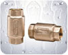
Spring-loaded, stem or cage poppet-style check valves should be used with submersible pumps (see Figure 1). They are designed to close quickly as the water flow stops and begins to move in a reverse direction. Swing-type check valves should not be used because they react too slowly. When the pump stops, there is a sudden reversal of flow before the swing check closes, causing a sudden change in the velocity of the water and a water hammer.
Installation
It is important to correctly choose and install a check valve to help ensure a trouble-free water system. Check valves should be properly sized to the pump’s flow and pressure conditions. Flow velocities should not exceed 10 feet per second (FPS), and 7 fps is a more conservative target maximum to avoid excessive pressure drop through the valve. The pressure rating of the check valve should exceed the maximum pressure output of the pump. Prior to installing a check valve, be certain its mechanism is operating properly. Be sure to install the valve with the flow arrow pointing in the proper direction.The materials of construction are an important consideration in ground water installations. Because conventional brass contains lead, it is against the law to use standard brass check valves in potable water well systems. Use no-lead bronze or brass, plastic, ductile iron or stainless steel.
Starting at the pump, the first check valve should be installed on or directly above the pump, unless you have a slow-producing well that sucks a little air from time to time. In this case, the first check should be installed at least 5 feet – and no more than 20 feet – above the pump to allow the pump to purge itself of air more easily on start-up. The second check valve never should be installed more than 25 feet above the lowest pumping level in the well. For deeper settings, it is recommended that a check valve be installed every 200 feet. Another check valve should be installed in the horizontal piping at the surface or just below the well seal or pitless adapter to hold pressure in the pressure tank when the pump is off (see Figure 2).
In addition to holding water pressure in the system when the pump stops, check valves also assist in the smooth operation of the water system, and extend its life by preventing backspin, up-thrust and water hammer.
Here are a few of the conditions that check valves help to control.
1. Backspin - With no check valve or if the check valve fails, the water in the drop pipe and the water in the system will flow back down the drop pipe and pump when the pump stops. This will cause the pump to rotate in a reverse direction as the water flows back down the pipe. If the pump motor were to be started while this is happening, a heavy strain would be placed on the pump/motor assembly, possibly causing the pump shaft to break or the motor thrust-bearing to be damaged.
2.Upthrust -With no check valve, or with a leaking check valve, the water in the drop pipe could drain back into the well, as stated in #1 above, and the pump would start under a reduced head condition. This can cause an upthrust on the impeller/shaft assembly. This upward movement carries across the pump/motor coupling and creates an upthrust condition in the motor. Repeated upthrust at each start can cause premature wear and failure of either the pump or the motor or both.
3.Water hammer -Water flowing through a piping system has kinetic energy (weight and velocity). When the pump stops, the water continues to move. Its energy must be absorbed in some way. The pressure tank normally absorbs this energy. However, in a system with leaking, slow-acting or too few check valves, the water will reverse direction momentarily. When it stops, the rapid dissipation of energy can cause a shock wave to travel through the piping. This is water hammer. It can split pipes, break joints and damage the pump. Water hammer varies in intensity, depending on the velocity with which the water is traveling, and how suddenly it stops. We will explore the subject of water hammer in detail in next month’s article.
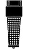
Foot valves (see Figure 3) are almost identical to check valves, but they have a screen attached to the inlet side. They are used to keep jet pumps primed, and are installed at the bottom of the suction pipe to prevent the water in the system from draining back into the well when the pump is off. This applies to both shallow-well jet pumps and deep-well jet pumps.
The use of good-quality spring-loaded check valves and foot valves is an important part of providing your customer with a water system that will perform reliably for years. ’Til next month ….
ND
The use of good-quality spring-loaded check valves and foot valves is an important part of providing your customer with a water system that will perform reliably for years. ’Til next month ….
ND

Report Abusive Comment