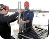
At a Spafford & Sons Inc. project, a submersible pump is prepared for installation.
The good folks at Franklin Electric have put together an excellent reference guide to ensure optimum operation of submersible pumps. This installation checklist article is excerpted from the company’s AIM Manual, which covers the application, installation and maintenance of submersibles. Franklin also has created a submersible motor installation record form that helps organize all the pertinent information related to a project. These items are included among a wealth of valuable information that is available at the company’s Web site: www.fele.com.
1. Motor Inspection
- Verify that the model, horsepower or kW, voltage, phase and hertz on the motor nameplate match the installation requirements.
- Check that the motor lead assembly is not damaged.
- Measure insulation resistance using a 500-volt or 1,000-volt DC megohmmeter from each lead wire to the motor frame. Resistance should be at least 200 megohms without drop cable.
- Keep a record of motor model number, horsepower or kW, voltage and serial number (stamped in shell above the nameplate. A typical example: S/N 07A18 01-0123).
2. Pump Inspection
- Check that the pump rating matches the motor.
- Check for pump damage, and verify that the pump shaft turns freely.
3. Pump/Motor Assembly
- If not yet assembled, check that pump and motor mounting faces are free from dirt, debris and uneven paint thickness.
- Pumps and motors over 5 HP should be assembled in the vertical position to prevent stress on pump brackets and shafts. Assemble the pump and motor together so their mounting faces are in contact, then tighten assembly bolts or nuts evenly to manufacturer specifications.
- If accessible, check that the pump shaft turns freely.
- Assemble the pump lead guard over the motor leads. Do not cut or pinch lead wires during assembly or installation.
4. Power Supply and Controls
- Verify that the power supply voltage, hertz and kVA capacity match motor requirements.
- Verify control box horsepower and voltage matches motor (three-wire only).
- Check that the electrical installation and controls meet all safety regulations and match the motor requirements, including fuse or circuit breaker size and motor overload protection. Connect all metal plumbing and electrical enclosures to the power supply ground to prevent shock hazard. Comply with national and local codes.
5. Lightning and Surge Protection
- Use properly rated surge (lightning) arrestors on all submersible pump installations. Motors 5 HP and smaller, which are marked “Equipped with Lightning Arrestors,” contain internal arrestors.
- Ground all aboveground arrestors with copper wire directly to the motor frame, or to metal drop pipe or casing that reaches below the well pumping level. Connecting to a ground rod does not provide good surge protection.
6. Electrical Drop Cable
- Use submersible cable sized in accordance with local regulations and the cable charts. Ground motor per national and local codes.
- Include a ground wire to the motor and surge protection, connected to the power supply ground if required by codes. Always ground any pump operated outside a drilled well.
7. Motor Cooling
- Ensure at all times that the installation provides adequate motor cooling.
8. Pump/Motor Installation
- Splice motor leads to supply cable using electrical grade solder or compression connectors, and carefully insulate each splice with watertight tape or adhesive-lined shrink tubing.
- Support the cable to the delivery pipe every 10 feet with straps or tape strong enough to prevent sagging. Use padding between cable and any metal straps.
- A check valve in the delivery pipe is recommended. More than one check valve may be required, depending on valve rating and pump setting.
- Assemble all pipe joints as tightly as practical to prevent unscrewing from motor torque. Torque should be at least 10 pound/feet per horsepower.
- Set the pump far enough below the lowest pumping level to assure the pump inlet always will have at least the net positive suction head (NPSH) specified by the pump manufacturer. Pump should be at least 10 feet from the bottom of the well to allow for sediment build up.
- Check insulation resistance as pump/motor assembly is lowered into the well. Resistance may drop gradually as more cable enters the water, but any sudden drop indicates possible cable, splice or motor lead damage.
9. After Installation
- Check all electrical and water line connections and parts before starting the pump.
- Start the pump and check motor amps and pump delivery. If normal, continue to run the pump until delivery is clear. If three-phase pump delivery is low, it may be running backward. Rotation may be reversed (with power off) by interchanging any two motor-lead connections to the power supply.
- Check three-phase motors for current balance within 5 percent of average, using motor manufacturer instructions. Imbalance over 5 percent will cause higher motor temperatures, and may cause overload trip, vibration and reduced life.
- Verify that starting, running and stopping cause no significant vibration or hydraulic shocks.
- After at least 15 minutes running time, verify that pump output, electrical input, pumping level and other characteristics are stable and as specified.

Report Abusive Comment