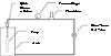
How
a pump test station could be plumbed.
You will perform electrical tests to determine if the problem is in the controls, the wiring or in the pump. You will measure the pressure and perform quick flow tests to see if there is a blockage in the pump or the plumbing, and to get a rough idea of the performance of the pump – if it is pumping at all. And, if these tests fail to identify the problem, or if the pump is not performing up to par, you will have to pull the pump, test and inspect it to make a final determination as to what the problem is, and whether or not the pump can be repaired.
In order to properly test the pump, you will need access to a pump test station. Your pump distributor likely has one, but if you are any distance away from their facility, it may be worth your time to build your own. The test station we describe is for a submersible pump, but it does not take much imagination to see that the same test station can be used to test any centrifugal pump.
Here is what you need:
1. A vessel of some sort into which you can submerse the pump. An old conventional galvanized tank with a 12-inch hole cut in the top works great for this. To make it easier to get the pump in and out of the tank, mount the tank at a 45-degree angle on a cradle. Then, using two lengths of 11⁄2-inch angle iron – long enough to reach from the top to the bottom of the tank – make a guide track for the pump to slide into the tank by spacing the rails about 3 inches apart. Weld a short piece of angle between the bottom ends to keep them together, and weld the top end to the lower side of the opening in the tank.
2. An accurate flow meter that has a large enough range to measure the flow rate of the largest pump you typically will service. If you service a range of pumps, from 5-gpm residential pumps to 75-gpm “gentleman farm” ag. pumps, you should consider two flow meters plumbed in parallel and valved so you can run the flow through either or both. This is because the accuracy and scale divisions of a 100-gpm flow meter are not precise enough in the lower range to be of much use.
3. An accurate pressure gauge. A 4-inch liquid-filled gauge with a range high enough to measure the shut-off pressure of the pumps you will be testing. Here again, two gauges that can be isolated – one with a low range, and one with a high range – may be helpful.
4. A quick disconnect device, like a union or cam and groove coupling to facilitate the attachment and removal of the pump from the piping system. A 6-foot length of high-pressure hose also is useful. Make sure it’s pressure rating is adequate.
5. A power supply, consisting of a motor starter for three-phase pumps and/or a control box for three-wire single-phase pumps. You can use your amp probe to measure the amp draw of your pump while it is running.
Note – If you will be testing straight centrifugal and jet pumps, plumb a line from the bottom of the tank to the suction side of the pump.
The illustration (on pg. 14) shows how a pump test station could be plumbed.
Here is how to test pumps using this test station.
1. Start with the valve in the closed position
2. Slowly turn on the pump, and open the valve to purge the air out of the pump.
3. Once the air has been purged, close the valve all the way, and note the pressure reading. This should correspond to the shut-off pressure on the pump curve. If it does not, there still is air in the pump, or it is worn from abrasion or old age. Disassemble the pump, and inspect for signs of wear.
4. Open the valve until water is flowing at approximately the flow rating of the pump, and note the pressure. Also note the amp reading at this flow rate, and compare these readings with values from the pump curve and motor manual. If there is a significant deviation from the book values, inspect the pump and motor to determine the problem.
5. Open the valve all the way, and note the flow rate, pressure and amp readings. Do not run the pump in this condition for very long because, with no backpressure on the discharge side, the pump could go into an up-thrust condition, which would damage the internals if left on for very long.
6. Plot these three values on the pump curve on the pump literature or manual. If the three points line up fairly closely, and the amp draw is at or below the book value, the pump is fine, and can be put back into service. If the flow characteristics vary more than 5 percent, or if the amp draw exceeds the book values, disassemble and inspect the pump, and either replace the defective parts or the whole pump.
You likely will find the parts you need at your local pump distributor. A simple test station like this can be a valuable tool that will take some of the guesswork out of your troubleshooting, and make you a better pump professional.
Here are examples of some of the components you will need.
- Flow meters
- Pressure gauges
- Cam and groove coupling
- Amp probe
- Galvanized tank (an old one will do)

Report Abusive Comment