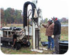
A variety of direct-push methods are available for installing temporary or permanent monitoring wells. The two main installation methods used are exposed-screen and protected-screen wells.
As with conventional well installations, hydraulic connections should not be created between otherwise isolated water-bearing strata. In addition, precautions should be taken to minimize turbidity during the installation of filter packs and the development and sampling of wells.
Exposed-screen Wells
With exposed-screen well installation methods, the well casing and screen are driven to the target depth using a single string of rods. Because the screen is exposed to formation materials while it is advanced, proper well development is important to remove soil from screen slots. This method is not recommended for installing well screens within or beneath contaminated zones because drag-down of contaminants with the screen may cross-contaminate sampling zones, and make acquisition of samples representative of the target zone impossible. Exposed-screen well installation methods should only be used in upgradient areas that are known to be uncontaminated. Also, some states prohibit allowing the formation to collapse around a well screen in the construction of a monitoring well. Therefore, state regulations should be consulted before selecting exposed-screen techniques.In one type of exposed-screen installation, the PVC well screen and casing are assembled and placed around a shaft of a drive rod connected to a metal drive tip. The casing and screen, which rest on top of the drive tip, are advanced to the target depth by driving the rod to avoid placing pressure on the screen. The drive tip slightly enlarges the hole to reduce friction between the formation and the well screen and casing, and remains in the hole plugging the bottom of the screen. The filter pack surrounding the well screen commonly is derived from formation materials that are allowed to collapse around the screen. Rigorous well development is necessary to remove formation fines and the effects of well installation, which may include borehole smearing or the compaction of formation materials. Due to the very small annulus (if any) that surrounds a well constructed using the exposed-screen method, it generally is not possible to introduce a filter pack or annular seal from the surface.
Exposed-screen methods also can be used to install well points – simple wells used for rapid collection of water-level data, ground water samples, and hydraulic test data in shallow unconfined aquifers. Well points generally are constructed of slotted steel pipe or continuous-wrap, wire-wound, steel screens with a tapered tip on the bottom. They can be driven into unconsolidated formations and used for either point-in-time sampling and decommissioned after the sample is collected, or left in place for the duration of the sampling program – possibly requiring the installation of a seal to prevent infiltration of water from the ground surface to the screened interval.
The optimum conditions for well point installations are shallow sandy materials. Predominantly fine-grained materials such as silt or clay can plug the screen slots as the well point is advanced. Because well points are driven directly into the ground with little or no annular space, the formation materials are allowed to collapse around the screen, and the well point needs to be developed to prepare it for sampling.
Protected-screen Wells
When installing a protected-screen well, the well casing and screen are either advanced within or lowered into a protective outer drive rod that already has been driven to the target depth. Once the well casing and screen are in place, the drive rod is removed. Alternatively, the casing, screen and a retractable shield may be driven simultaneously to the target depth. Once in place, the screen is exposed, and the entire unit remains in the ground. If there is sufficient clearance between the inside of the drive rod and the outside of the well casing and screen, a filter pack and annular seal may be installed by tremie from the surface as the drive casing is removed from the hole. Several filter packing and annular sealing approaches are available, depending on the equipment used for the installation. Regardless of the method of installation, the filter pack should be sized appropriately to retain most of the formation materials.The most common protected-screen method for installing direct-push wells is to advance an outer drive casing equipped with an expendable drive tip to the target depth. The well casing and screen then are assembled, lowered inside the drive casing, and anchored to the drive tip. The drive casing seals off the formations through which it has been advanced, protecting the well casing and screen from clogging and from passing through potentially contaminated intervals. The position and length of the screen should be selected to match the thickness of the monitoring zone, which can be determined by using additional information, such as CPT logs or continuous soil boring logs.
When direct-push wells are installed in non-cohesive, coarse-grained formations, the formation can be allowed to collapse around the screen (if this technique is not prohibited by state well installation regulations) after it is placed at the target depth, since turbidity problems are unlikely. When turbidity is likely to pose a problem for ground water sample quality, a number of methods for installing filter packs are available. The filter pack can be poured or tremied into place as the drive casing is removed. Depending on the relative size of the drive casing and well, however, it may be difficult to introduce filter pack or annular seal materials downhole unless the hole is in a cohesive formation that will remain open as the drive casing is removed. Typical inside diameters of direct-push wells range from 0.5-inch (schedule 80 PVC) to 2 inches (schedule 40 PVC), and the maximum inside diameter of drive casing is 3.5 inches.
For the best control of filter pack placement and grain size, sleeved or pre-packed well screens can be used. Pre-packed screens generally are composed of a rigid Type I PVC screen surrounded by a pre-sized filter pack. The filter pack is held in place by a stainless-steel wire mesh (for organic contaminants) or food-grade plastic mesh (for inorganic contaminants), such as polyethylene, that is anchored to the top and bottom of the screen. Sleeved screens consist of a stainless-steel wire mesh jacket filled with a pre-sized filter-pack material, which can be slipped over a PVC pipe base with slots of any size. Although sleeve thickness generally ranges from only 0.25 inches to 0.5 inches, it has been shown to provide an effective filter pack.
Annular seals and grout should be placed above the filter pack to prevent infiltration of surface runoff, and to maintain the hydraulic integrity of confining or semi-confining layers, where present. The sealing method used depends on the formation, the well installation method, and the regulatory requirements of state or local agencies. Most protected-screen installations tremie a high-solids (at least 20% solids) bentonite slurry or neat cement grout into place as the drive casing is removed from the hole. A barrier of fine sand or granular or pelletized bentonite (where water is present) may be placed above the primary filter pack before grouting to protect it from grout infiltration, which could alter the water chemistry in the screened zone. Similar to the pre-packed and sleeved screens mentioned above, modular bentonite sleeves that attach to the well screens and are advanced with the well during installation also are available. Some manufacturers provide a foam seal that expands immediately when the casing is withdrawn to form a temporary seal above the screen. A bentonite sleeve above the seal expands more slowly after the casing is withdrawn, but forms a permanent seal once it hydrates.
To ensure a complete seal of the annular space from the top of the annular seal to the ground surface, the grout or slurry should be placed from the bottom up. By using a high-pressure grout pump and nylon tremie tube, it is possible to perform bottom-up grouting in the small annular spaces of direct-push equipment. Slurries of 20 percent to 30 percent bentonite or neat cement grout most commonly are used to meet state regulatory requirements.
A properly constructed direct-push-installed monitoring well can provide representative water-quality samples and protect ground water resources. A fairly recent study demonstrated that wells installed in this manner beneath highly contaminated source zones consistently provided non-detect values. In addition, as with conventional wells, a properly constructed well should have a flush-mount or above-ground well protection to prevent physical damage or tampering of the well.
ND
This article is provided through the courtesy of the U.S. Environmental Protection Agency’s Office of Solid Waste and Emergency Response. It is excerpted from the publication, “Groundwater Sampling and Monitoring with Direct Push Technologies.”
Report Abusive Comment