
The deck I discussed last month is looking good although the boards have shrunk a little bit—it’s OK, though. It is time to get back to our discussion of well screens.
You will remember from my writing of two months ago that, in the post-World War II era, with higher capacity pumps we were experiencing some well screen difficulties—mainly that they were plugging up way too quickly. My father and I discussed this problem at length, especially after we changed a few screens at no charge feeling that our customer didn’t get value received. We also did some research, talked to drillers, screen company reps and others, and decided we needed to go to larger-diameter wells with larger-diameter screens, and those of a different design.
We had been installing pipe base screens, which were kind of the bread-and-butter model used around here for many years. If you tear one of these apart you, will see that the pipe base has rectangular holes punched in it covered by a fine gauze with varying degrees of mesh. The gauze is given a final covering of brass sheet with holes punched in it as protective layer. I will say these screens are rugged, but they were made of three or four dissimilar metals if you count the steel in the pipe, the zinc galvanizing, the copper mesh and the brass outer shell. These dissimilar metals can, in the right waters, really create a corrosion redeposition issue.
|
|
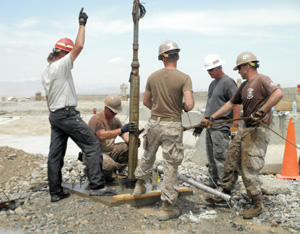
Deployed Seebees work to repair a submersible well pump. Veteran driller and columnist John Schmitt says submersibles really became viable during the mid- to late-1950s. Source: Chief Petty Officer David Asbury / U.S. Navy |
The biggest problem with this design is, though, that it has very limited open area. The punched openings, even if totally open, are a small percentage of the pipe base. Cover that with a gauze, and you have reduced the open area a whole bunch. And then, cover this with a brass jacket with fairly small holes and you have a screen with very limited open area. Now, if you think I’m making a case for the highest possible open area in a screen, you’re right. My experience over the last 60 years is what I will use for a backup. Generally, an inlet velocity for water at the screen is recommended to be no more than 1⁄10th of a foot per second or 1.2 inches per second. And I have talked with industry professionals who believe that that figure should be 1⁄20th of a foot per second or .6 inches. Blank pipe or wires will not let any water into the wells, no matter who makes it.
In any event, my father and I decided to give up on 2-inch wells in the early 1950s and go all the way to 3-inch wells. The 3-inch size had some of the disadvantages of the 2-inch, in that you still had to use a jet pump, at least back then. But you could get a bigger diameter screen in and we decided to go to wire round screens of a bronze material. I have to say these have lasted, lasted and lasted. I have had to acidize a few but, overall, they were a huge improvement over 2-inch wells and the 1.25-inch screens we put in them.
By the mid- to late-1950s, the submersible pump was becoming a viable product and we went to drilling 4-inch wells by the cable tool method, as my long time readers are no doubt aware. We used wire-wound bronze screens in these, and later stainless steel. These products just about eliminated screen problems. I have a few wells that I drilled in the mid 1950s with these screens, and they are still producing plenty of water and have never been acidized or cleaned.
For this column, I did some calculating of screen capacities from the technical information from a major screen manufacturer. I calculated that a 3-foot screen in a 2-inch well with 12-slot openings (.012 inches) is capable of producing just under 10 gpm. A 15-slot screen of the same length in the same well is rated at 12 gpm. Either of these screens will handle most any jet pump in domestic use.
To show the increase by going to a 4-inch well, a 12-slot screen that is 4-foot long in that well is rated at 28 gpm and a 20-slot, admittedly a little coarser, is rated at 43 gpm. Both of these figures would be beyond what an average domestic well is equipped for in this area. Just for the fun of it, I calculated the rating of the screen in the well at my home. This well is a 6-inch steel-cased well, 179 feet deep with 7 feet of 50-slot (.05 inches) stainless steel screen. It is rated to produce 208 gpm, which is nice as we test pumped it at about 250 gpm when we drilled it in 1989—just a nice little house well.
After learning some screen lessons the hard way, I can remember my father and I reading about screens that were lasting up to 15 years before they needed to be cleaned. Now, these were generally in industrial wells, but we laughed anyhow when we thought that they could not possibly go that long without plugging up. The fact that we have wells from the 1950s and 1960s still going strong, admittedly in domestic and farm situations, has proved how wrong we were.
Now you understand of course, that the slot sizes and length of screen are determined by the formations or aquifers themselves. As I said in my article two months back, a 6-foot screen in 21⁄2-feet of formation isn’t going to work very well. Next time, I will discuss determining proper slot sizes and installation methods, of which there are several.
We have been through some extremely hot, humid, unpleasant weather here in Michigan, but it has cooled off as we approach the month of August. It is warm but generally pleasant. Those fellows with the new irrigation wells haven’t used them much, as we have had good rain. Pretty much every driller and pump man I know is busy, and that is nice to hear.


Report Abusive Comment