Affinity Law 1 - As an AC induction motor slows, the flow rate drop-off is proportional to the speed. If the RPM is cut in half, the flow rate drops in half.
Affinity Law 2 - As the RPM is reduced, the pressure drops off as the square of the speed. If the RPM is cut in half, the pressure output of the pump drops to one-fourth of its full speed capability.
Affinity Law 3 - As the RPM is reduced, the horsepower required to operate the pump drops as the cube of the speed. Cutting the RPM in half reduces the horsepower to one-eighth of that required to run the pump at full speed.
From that, you can see how a system with a pump sized for a peak load, but operated at less than peak most of the time, may justify the use of a VFD, assuming that the head requirements still are met at the slower speed.
VFDs are not for everyone. The primary limitation to the use of VFDs for pumping applications has to do with the second affinity law, which, as we said, states that pressure falls off as the square of the speed. If the pressure side of your system curve cannot be satisfied at a slower speed, you are limited as to how slow you can run the pump, and the energy savings will be limited accordingly.
The other area where VFDs may not be right for pumping applications is when there is a long distance between the drive and the pump motor. This can be a particular problem in a submersible application, because the motor is down in the well, and the drive is on the surface.
The problem has to do with type of wave form and voltage spikes created by VFDs. Without getting too detailed, these distorted wave forms and voltage spikes can damage motor windings. This is particularly critical in small motors due to the geometry of the windings, and in motors built with no phase paper between the windings. Luckily, most motors used in pumping applications have phase paper, and most are not small, but there are many well applications where long lead lengths are unavoidable. Consult the motor manufacturer if your motor is more than 200 feet from the drive. They may recommend the use of an output line filter to protect the motor windings.
Larger Pumping Applications
1. The enclosure -It should be suitable for the environment into which the VFD will be subjected. VFDs are temperature-sensitive, typically having a 104 degree F to 122 degree F upper ambient limit. If they will be installed in an area where the temperature can exceed these numbers, they should be in a fan-cooled, filtered enclosure as a minimum, or in an air-conditioned enclosure or building. Additionally, they should be protected from dust and the elements. Ideally, a VFD for a large water well should be in a NEMA 12 enclosure in an air-conditioned weatherproof building at the well head.2. Bypass -If your VFD pump application is such that it would not be good for the pump to be offline, an across-the-line bypass should be included, consisting of three contactors - two to isolate the drive, and one to start the pump across the line, when the VFD is taken offline for service. The two isolation contactors can be smaller than the across-the-line starter contactor because they do not need to handle the in-rush starting current. Additionally, only the starter contactor needs overload protection, because VFD drives come with built-in motor protection.3. Interfaces - Pressure transducers are the most common control interfaces used in pumping applications. They allow the pump to maintain a constant system pressure as the load varies. They vary in price from less than $100 to more than $1,000. For best results, use a good precision pressure transducer.
Direct or remote-reading flow meters are common system interfaces to allow the installer to properly set up the VFD, and to allow the operator to monitor the system performance. Adding remote reading pressure and flow meters to the panel front is a nice touch.
4. Sizing VFDs for the service factor of the motor - As you know, most pump manufacturers design their pumps to work into the service factor horsepower range of the motor, typically 115 percent of rated horsepower. If your application requires the pump to operate in “service factor” as it is called, make sure the drive is sized accordingly. Unless ordered otherwise, they will be sized for a service factor of 1.0
5. Programmability - To make programming easier, an English operator keypad interface is highly recommended. It makes calibration a matter of following real English instructions rather than entering meaningless codes and following complicated instructions in the manual.
6. Acceleration time - There is a pumping-specific program parameter that your drive may need. Motor manufacturers limit the frequency range within which their motors can be operated, and some limit the acceleration time through the lower frequency threshold. This may mean your drive must be capable of accelerating rapidly, say in 1 second, through 30 Hz, and then slow down for the rest of the acceleration to reduce in-rush current, and to avoid overshooting the pressure set point.
7. Additional contacts - There also may be a need for an additional set or two of contacts to operate ancillary devices like lubricators, air chargers, etc.
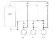
Multiplex System
We'll close this series on VFDs with a schematic for operating several pumps from one VFD (see Figure 1). The scenario is a system with a varying load requiring up to three pumps to handle the full load. The idea is to use a single VFD, which takes pump #1 up to 33 percent of the load, at which point pump #1 goes across the line, and the drive takes pump #2 to 66 percent, at which point #2 goes across the line, and the drive picks up #3. There are some tricks that must be employed, but the drive manufacturers know how to do them - so, if you have an application with two or more pumps on the same system, ask your drive supplier to quote a multiplex system.
Next month, we will shift our focus from pumps and motors to wells, and talk about water well performance curves and their relationship to pump selection. 'Til then ….
ND


Report Abusive Comment